
What Does It Take to Make a Kernel?
The kernel this. The kernel that. People often refer to one operating system's kernel or another without truly knowing what it does or how it works or what it takes to make one. What does it take to write a custom (and non-Linux) kernel?
So, what am I going to do here? In June 2018, I wrote a guide to build a complete Linux distribution from source packages, and in January 2019, I expanded on that guide by adding more packages to the original guide. Now it's time to dive deeper into the custom operating system topic. This article describes how to write your very own kernel from scratch and then boot up into it. Sounds pretty straightforward, right? Now, don't get too excited here. This kernel won't do much of anything. It'll print a few messages onto the screen and then halt the CPU. Sure, you can build on top of it and create something more, but that is not the purpose of this article. My main goal is to provide you, the reader, with a deep understanding of how a kernel is written.
Once upon a time, in an era long ago, embedded Linux was not really a thing. I know that sounds a bit crazy, but it's true! If you worked with a microcontroller, you were given (from the vendor) a specification, a design sheet, a manual of all its registers and nothing more. Translation: you had to write your own operating system (kernel included) from scratch. Although this guide assumes the standard generic 32-bit x86 architecture, a lot of it reflects what had to be done back in the day.
The exercises below require that you install a few packages in your preferred Linux distribution. For instance, on an Ubuntu machine, you will need the following:
- binutils
- gcc
- grub-common
- make
- nasm
- xorriso
Note: I'm going to simplify things by pretending to work with a not-so-complex 8-bit microprocessor. This doesn't reflect the modern (and possibly past) designs of any commercial processor.
When the designers of a microprocessor create a new chip, they will write some very specialized microcode for it. That microcode will contain defined operations that are accessed via operation codes or opcodes. These defined opcodes contain instructions (for the microprocessor) to add, subtract, move values and addresses and more. The processor will read those opcodes as part of a larger command format. This format will consist of fields that hold a series of binary numbers—that is, 0s and 1s. Remember, this processor understands only high (the 1s) and low (the 0s) signals, and when those signals (as part of an instruction) are fed to it in the proper sequence, the processor will parse/interpret the instruction and then execute it.
Here's the rundown of the command structure for the made-up processor:
- 0, 1 — opcode
- 2, 3 — source 1
- 4, 5 — source 2
- 6, 7 — destination
Now, what exactly is assembly language? It's as close to machine code as you can get when programming a microprocessor. It is human-readable code based on the machine's supported instruction set and not just a series of binary numbers. I guess you could memorize all the binary numbers (in their proper sequence) for every instruction, but it wouldn't make much sense, especially if you can simplify code writing with more human-readable commands.
This make-believe and completely unrealistic processor supports only four instructions of which the ADD instruction maps to an opcode of 00 in binary code, and SUB (or subtract) maps to an opcode of 01 in binary. You'll be accessing four total CPU memory registers: A or 00, B or 01, C or 10 and D or 11.
Using the above command structure, your compiled code will send the following instruction:
ADD A, B, C
Or, "add the contents of A and B and store them into register C" in the following binary machine language format:
00000110
Let's say you want to subtract A from C and store it in the D register. The human-readable code would look like the following:
SUB C, A, D
And, it will translate to the following machine code for the processor's microcode to process:
01100011
As you would expect, the more advanced the chip (16-bit, 32-bit, 64-bit), the more instructions and larger address spaces are supported.
The Boot CodeThe assembler I'm using in this tutorial is called NASM. The open-source NASM, or the Net-Wide Assembler, will assemble the assembly code into a file format called object code. The object file generated is an intermediate step to produce the executable binary or program. The reason for this intermediate step is that a single large source code file may end up being cut up into smaller source code files to make them more manageable in both size and complexity. For instance, when you compile the C code, you'll instruct the C compiler to produce only an object file. All object code (created from your ASM and C files) will form bits and pieces of your kernel. To finalize the compilation, you'll use a linker to take all necessary object files, combine them, and then produce the program.
The following code should be written to and saved in a file named boot.asm. You should store the file in the dedicated working directory for the project.
boot.asm
bits 32

section .multiboot               ;according to multiboot spec
        dd 0x1BADB002            ;set magic number for
                                 ;bootloader
        dd 0x0                   ;set flags
        dd - (0x1BADB002 + 0x0)  ;set checksum

section .text
global start
extern main                      ;defined in the C file

start:
        cli                      ;block interrupts
        mov esp, stack_space     ;set stack pointer
        call main
        hlt                      ;halt the CPU

section .bss
resb 8192                        ;8KB for stack
stack_space:
So, this looks like a bunch of nonsensical gibberish, right? It
isn't. Again, this is supposed to be human-readable code. For instance,
under the multiboot section, and in the proper order of the
multiboot specification (refer to the section labeled "References"
below), you're defining three double words variables. Wait,
what? What is a double word? Well, let's take a step back. The
assembly DD pseudo-instruction translates to Define Double (word),
which on an x86 32-bit system is 4 bytes (32-bits). A DW or Define
Word is 2 bytes (or 16 bits), and moving even further backward, a DB or
Define Byte is 8-bits. Think of it as your integers,
short and long in your high-level
coding languages.
Note: pseudo-instructions are not real x86 machine instruction. They are special instructions supported by the assembler and for the assembler to help facilitate memory initialization and space reservation.
Below the multiboot section, you have a section labeled
text, which is shortly followed by a function labeled
start. This start function will set up the
environment for your main kernel code and then execute that kernel
code. It starts with a cli. The CLI command, or Clear
Interrupts Flag, clears the IF flag in the EFLAGS register. The following
line moves the empty stack_space function into the Stack
Pointer. The Stack Pointer is small register on the microprocessor
that contains the address of your program's last request from a
Last-In-First-Out (LIFO) data buffer referred to as a Stack. The example assembly
program will call the main function defined in your C file
(see below) and then halt the CPU. If you look above, this is telling
the assembler via the extern main line that the code for
this function exists outside this file.
So, you wrote your boot code, and your boot code knows that there is an external
main function it needs to load into, but you don't have an
external main function—at least, not yet. Create a file
in the same working directory, and name it kernel.c. The
file's contents should be the following:
kernel.c
#define VGA_ADDRESS 0xB8000   /* video memory begins here. */

/* VGA provides support for 16 colors */
#define BLACK 0
#define GREEN 2
#define RED 4
#define YELLOW 14
#define WHITE_COLOR 15

unsigned short *terminal_buffer;
unsigned int vga_index;

void clear_screen(void)
{
    int index = 0;
    /* there are 25 lines each of 80 columns;
       each element takes 2 bytes */
    while (index < 80 * 25 * 2) {
            terminal_buffer[index] = ' ';
            index += 2;
    }
}

void print_string(char *str, unsigned char color)
{
    int index = 0;
    while (str[index]) {
            terminal_buffer[vga_index] = (unsigned
             ↪short)str[index]|(unsigned short)color << 8;
            index++;
            vga_index++;
    }
}

void main(void)
{
    /* TODO: Add random f-word here */
    terminal_buffer = (unsigned short *)VGA_ADDRESS;
    vga_index = 0;

    clear_screen();
    print_string("Hello from Linux Journal!", YELLOW);
    vga_index = 80;    /* next line */
    print_string("Goodbye from Linux Journal!", RED);
    return;
}
If you scroll all the way to the bottom of the C file and look inside the
main function, you'll notice it does the following:
- Assigns the start address of your video memory to the string buffer.
- Resets your internal location marker for where you are in that string buffer.
- Clears the terminal screen.
- Prints a message (in one color).
- Sets your internal location marker for the next line.
- Prints another message (in another color).
- And, returns back to the boot code (where, if you recall, it halts the CPU).
In the current x86 architecture, your video memory is running in protected
mode and starts at memory address 0xB8000. So, everything
video-related will start from this address space and will support up
to 25 lines with 80 ASCII characters per line. Also, the video mode in
which this is running supports up to 16 colors (of which I added a
few to play with at the top of the C file).
Following these video definitions, a global array is defined to map to the video memory and an index to know where you are in that video memory. For instance, the index starts at 0, and if you want to move to the first character space of the next line on the screen, you'll need to increase that index to 80, and so on.
As the names of the following two functions imply, the first clears
the entire screen with an ASCII empty character, and the second
writes whatever string you pass into it. Note that the expected
input for the video memory buffer is 2 bytes per character. The first
of the two is the character you want to output, while the second is
the color. This is made more obvious in the print_string() function,
where the color code is actually passed into the function.
Anyway, following those two functions is the main routine
with its actions already mentioned above. Remember, this is a learning
exercise, and this kernel will not do anything special other than print
a few things to the screen. And aside from adding real functions, this
kernel code is definitely missing some profanity. (You can add
that later.)
In the real world...
Every kernel will have a main() routine (spawned by
a bootloader), and within that main routine, all the proper system
initialization will take place. In a real and functional kernel, the
main routine eventually will drop into an infinite while()
loop where all future kernel functions take place or spawn a thread
accomplishing pretty much the same thing. Linux does this as well. The
bootloader will call the start_kernel() routine found in
init/main.c, and in turn, that routine will spawn an init
thread.
As mentioned previously, the linker serves a very important purpose. It is what will take all of the random object files, put them together and provide a bootable single binary file (your kernel).
linker.ld
OUTPUT_FORMAT(elf32-i386)
ENTRY(start)
SECTIONS
 {
   . = 1M;
   .text BLOCK(4K) : ALIGN(4K)
   {
       *(.multiboot)
       *(.text)
   }
   .data : { *(.data) }
   .bss  : { *(.bss)  }
 }
Let's set the output format to be a 32-bit x86 executable. The entry
point into this binary is the start function from your
assembly file, which eventually loads the main program
from the C file. Further down, this essentially is telling the linker
how to merge your object code and at what offset. In the linker file,
you explicitly specify the address in which to load your kernel binary. In
this
case, it is at 1M or a 1 megabyte offset. This is where the main kernel
code is expected to be, and the bootloader will find it here when it is
time to load it.
The most exciting part of the effort is that you can piggyback off the very popular GRand Unified Bootloader (GRUB) to load your kernel. In order to do this, you need to create a grub.cfg file. For the moment, write the following contents into a file of that name, and save it into your current working directory. When the time comes to build your ISO image, you'll install this file into its appropriate directory path.
grub.cfg
set timeout=3

menuentry "The Linux Journal Kernel" {
        multiboot /boot/kernel
}
Compilation Time
Build the boot.asm into an object file:
$ nasm -f elf32 boot.asm -o boot.o
Build the kernel.c into an object file:
$ gcc -m32 -c kernel.c -o kernel.o
Link both object files and create the final executable program (that is, your kernel):
$ ld -m elf_i386 -T linker.ld -o kernel boot.o kernel.o
Now, you should have a compiled file in the same working directory labeled
kernel:
$ ls
boot.asm  boot.o  grub.cfg  kernel  kernel.c  kernel.o
 ↪linker.ld
This file is your kernel. You'll be booting into that kernel shortly.
Building a Bootable ISO ImageCreate a staging environment with the following directory path (from your current working directory path):
$ mkdir -p iso/boot/grub
Let's double-check that the kernel is a multiboot file type (no output is expected with a return code of 0):
$ grub-file --is-x86-multiboot kernel
Now, copy the kernel into your iso/boot directory:
$ cp kernel iso/boot/
And, copy your grub.cfg into the iso/boot/grub directory:
$ cp grub.cfg iso/boot/grub/
Make the final ISO image pointing to your iso subdirectory in your current working directory path:
$ grub-mkrescue -o my-kernel.iso iso/
xorriso 1.4.8 : RockRidge filesystem manipulator,
 ↪libburnia project.

Drive current: -outdev 'stdio:my-kernel.iso'
Media current: stdio file, overwriteable
Media status : is blank
Media summary: 0 sessions, 0 data blocks, 0 data, 10.3g free
Added to ISO image: directory '/'='/tmp/grub.fqt0G4'
xorriso : UPDATE : 284 files added in 1 seconds
Added to ISO image: directory
 ↪'/'='/home/petros/devel/misc/kernel/iso'
xorriso : UPDATE : 288 files added in 1 seconds
xorriso : NOTE : Copying to System Area: 512 bytes from file
 ↪'/usr/lib/grub/i386-pc/boot_hybrid.img'
ISO image produced: 2453 sectors
Written to medium : 2453 sectors at LBA 0
Writing to 'stdio:my-kernel.iso' completed successfully.
Additional Notes
Say you want to expand on this tutorial by automating the entire process of building the final image. The best way to accomplish this is by throwing a Makefile into the project's root directory. Here's an example of what that Makefile would look like:
Makefile
CP := cp
RM := rm -rf
MKDIR := mkdir -pv

BIN = kernel
CFG = grub.cfg
ISO_PATH := iso
BOOT_PATH := $(ISO_PATH)/boot
GRUB_PATH := $(BOOT_PATH)/grub

.PHONY: all
all: bootloader kernel linker iso
    @echo Make has completed.

bootloader: boot.asm
    nasm -f elf32 boot.asm -o boot.o

kernel: kernel.c
    gcc -m32 -c kernel.c -o kernel.o

linker: linker.ld boot.o kernel.o
    ld -m elf_i386 -T linker.ld -o kernel boot.o kernel.o

iso: kernel
    $(MKDIR) $(GRUB_PATH)
    $(CP) $(BIN) $(BOOT_PATH)
    $(CP) $(CFG) $(GRUB_PATH)
    grub-file --is-x86-multiboot $(BOOT_PATH)/$(BIN)
    grub-mkrescue -o my-kernel.iso $(ISO_PATH)

.PHONY: clean
clean:
        $(RM) *.o $(BIN) *iso
To build (including the final ISO image), type:
$ make
To clean all of the build objects, type:
$ make clean
The Moment of Truth
You now have an ISO image, and if you did everything correctly, you should be able to boot into it from a CD on a physical machine or in a virtual machine (such as VirtualBox or QEMU). Start the virtual machine after configuring its profile to boot from the ISO. You'll immediately be greeted by GRUB (Figure 1).
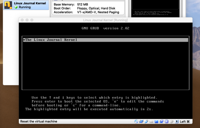
Figure 1. The GRUB Bootloader Counting Down to Load the Kernel
After the timeout elapses, the kernel will boot.
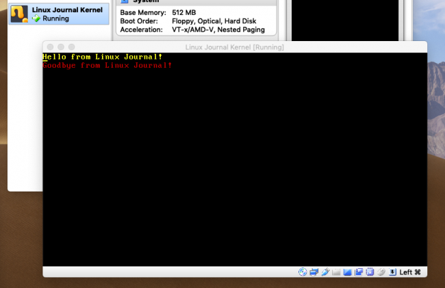
Figure 2. The Linux Journal kernel booted. Yes, it does only this.
SummaryYou did it! You wrote your very own kernel from scratch. Again, it doesn't do much of anything, but you definitely can expand upon this. Now, if you will excuse me, I need to post a message to the USENET newsgroup, comp.os.minix, about how I developed a new kernel, and that it won't be big and professional like GNU.
Resources- "DIY: Build a Custom Minimal Linux Distribution from Source" by Petros Koutoupis, LJ, June 2018
- "Build a Custom Minimal Linux Distribution from Source, Part II" by Petros Koutoupis, LJ, January 2019
- The Required Fields for the Multiboot Header
- The Computer Display Common Text Modes
- The Official NASM Project Page

Petros Koutoupis, LJ Editor at Large, is currently a senior performance software engineer at Cray for its Lustre High Performance File System division. He is also the creator and maintainer of the RapidDisk Project. Petros has worked in the data storage industry for well over a decade and has helped pioneer the many technologies unleashed in the wild today.
Recent Articles


