Put a Sump Pump on the Web with Embedded Linux
My wife and I bought our house in the summer of 1996. In early spring of 1997, the basement filled with water. In early spring of 1998, the basement filled with water. In early spring of 2001, the basement filled with water. Fed up with the basement filling with water, we decided it was time to install a sump pump.
Late in 2003, looking up the hill at more than four feet of snow waiting to flood our basement, we realized we never got around to installing the sump pump we decided to get in 2001. This time we vowed we really were going to do something, and we did. After a week of jackhammering the basement, we had ourselves a shiny new sump pump complete with a perimeter drain, battery backup and snazzy cover. Not trusting the ability of this little pump to eject all that melting snow, I become obsessed with the sump. I checked the water level every ten minutes. I woke up at night to check the water level. I called home from work to get a report—it was getting absurd. The very thing that was supposed to make me sleep easier was suddenly consuming me. Then it dawned on me: why not rig up a contraption that would let me monitor the pump remotely? I established some goals for the project: 1) do not in any way burn the house down, 2) do not in any way cause the pump to stop working, and 3) learn something.
In accordance with my primary and secondary goals, I decided I would not place any new circuitry in series with the pump's power. In addition to the obvious dangers of running 10 amps through a circuit I constructed, a fair amount of isolation circuitry would be required to ensure I didn't fry the processor to which I was going to connect. One option was to wrap a coil of wire around the current-carrying conductor in the pump's cord. Presumably, after suitable signal conditioning, the induced voltage would be detectable at the processor. Unfortunately, given that my home electronics lab is pretty meager, this method likely would take too long to develop.
After rejecting several other ideas, I went to Google. Eventually, I was reminded of a phenomenon known as the Hall Effect. The Hall Effect is a manifestation of the Lorentz force acting on electrons flowing in the presence of a magnetic field. The Lorentz force acts normal to both the electric and magnetic fields, causing the electrons to have a non-uniform distribution in the direction of the Lorentz force. The voltage induced on the surface of the conductor in this direction is proportional to the magnetic field strength and therefore can be used to detect its strength. A wide variety of Hall Effect sensors are available commercially, differing in the amount of signal conditioning they provide internally and the magnetic field strengths to which they are sensitive. For this application, I chose the Allegro Microsystems A3240LUA, a fairly sensitive unipolar sensor; a datasheet is available at www.allegromicro.com/sf/3240. A unipolar sensor basically acts as an NPN transistor whose base current is on when the device is in the presence of a south magnetic pole.
I acquired a few of the sensors with which to experiment. My hope was the remote sensor would consist of nothing more than the Hall effect device connected to a general-purpose input/output (GPIO) pin on the processor. To ease the software debugging, I decided to construct a standalone circuit that would indicate whether the pump was on by way of an LED. This would boost my confidence that the sensor was capable of detecting the current. I constructed the circuit shown in Figure 1.
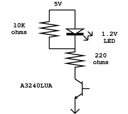
Figure 1. Schematic of the Test Circuit
I plugged the batteries in, waved a magnet in front of the sensor and, as expected, the LED came on. The next step was to wait for the pump to come on and wave the sensor near the power cord to see if it could detect the near field. Wait, wave, nothing; wait, wave, nothing. It appeared that the near-field/far-field boundary was much closer to the conductors than I had originally thought. The magnetic fields of the hot and neutral leads in the power cord were close enough to cancel one another, so I couldn't detect them. No matter where I placed the sensor, I couldn't detect the current. Not to be dissuaded, I came up with a slight modification to the plan. Armed with an old 15-amp extension cord and a piece of soft iron core, I set about strengthening the field by wrapping about ten turns of the neutral lead around the iron core. A couple of wire ties and a bit of epoxy completed the job. With my modified cord, I headed down to the sump. After plugging the pump into the extension cord, I waited for some activity. When the pump came on this time, I was able to get the test sensor close enough to the iron core to detect the field. With a bit of perf board, some solder and a bit more epoxy, the final sensor was completed. Figure 2 shows the finished sensor.
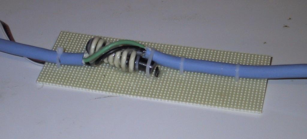
Figure 2. The Finished Sensor
The next decision to make was what sort of a processor to use. The main considerations were price, presence of onboard Ethernet, available GPIOs and the ability to run Linux. After searching for a while, I came to the conclusion that a number of embedded microcontrollers were available that had Ethernet and enough horsepower for this task, but most didn't explicitly mention Linux. At the other end of the spectrum were the PC/104 class embedded PCs, which significantly offered more muscle and cost than was needed for this project. I ended up with a Net4501 from Soekris Engineering, a single-board computer with a CompactFlash socket, 64MB of RAM, an AMD Elan processor and three onboard Ethernet controllers. As an extra bonus, the board has the ability to boot over the network through the Preboot Execution Environment (PXE).
The documentation on the Soekris Web site (www.soekris.com) made it clear that several of the Elan's GPIO pins were available on a readily accessible header, along with a +5V supply. The price was quite reasonable and included a power supply and a nifty metal case to hold the board. Each of Elan's GPIO pins has an internal pull-up or pull-down. Selecting one with an internal pull-up allowed me to connect the bare sensor to the CPU without any other components.
Next, I built a recent (2.4.19) kernel capable of being network-booted and disabled almost everything. I built the kernel with no modules and enabled the Natsemi Ethernet driver, root NFS, serial console and the SC520 watchdog timer. In addition to the normal configuration process, an additional change to the kernel was required for this project. In the 2.4 series of kernels, the default timer interrupt for x86 is set to 100Hz. Because I knew I'd be sampling a signal running at nearly the same frequency (60Hz), I decided to increase the timer frequency. The interrupt timer frequency is controlled by the Hz define in asm/param.h. The upper boundary on this value is 2K, so I set mine to 1,500 to provide me with 1,500 timer interrupts per second. With little else running on the machine, there would be no real likelihood of timer-based routines interfering with one another due to the increased frequency.
I configured my DHCP server and PXELINUX to serve up the previously built kernel. All that was left was to populate the root filesystem for the TFTP sever. To create the initial runtime environment, I built the latest uClibc, BusyBox, TinyLogin and utelnetd packages. I statically linked all three executables against uClibc. BusyBox's version of init starts up a shell on the console port by default. To add other features, I added my own /etc/inittab. It enables the console shell and invokes a simple init script that initially (re)mounts the root filesystem, enables the watchdog and starts a telnetd so I can connect remotely. With a terminal connected to the serial console port, I rebooted the device. Through the console port I was able to see the system load and eventually drop into the BusyBox version of the shell.
Once the system was up and running, it was time to focus on the new drivers. The only kernel-space device driver needed for this project is something to monitor the GPIO pin to which the sensor is connected. Because I am new to kernel programming, I decided to minimize the likelihood of anything going wrong in the kernel by limiting this driver to the smallest possible amount of code. To that end, I decided to write a /proc filesystem driver that simply would report the state of the pump as on or off. Any other work that needed to use user-space programs would poll the low-level driver.
The driver's init function performs three main tasks. First, it registers itself as a /proc filesystem module with the create_proc_entry call. The two important structures the proc_dir_entry returned are the file and inode operations tables, which are set to two static structures with entries filled out appropriately. Because this is such a simple module, the vast majority of the entries in both structures are NULL. Once the proc entry has been created, the init routine pokes a few Elan-specific registers to make sure the desired GPIO is set as an input.
The last thing the initialization routine does is kick off a timer to check the pin at regular intervals. The timer function bears a bit more exploration:
static void sample( unsigned long data ){

  static int remaining_samples = 0;
  __u16 dat;
  int ntimeout = 1;
  int mtimeout = Hz*mper - nsamp*ntimeout;

  if ( remaining_samples ){
    /*
     * Take another microsample
     */
    timer.expires = jiffies + ntimeout;
    remaining_samples--;
    dat = readw( pio_dat ) & DMASK;
    if ( dat == 0 ){
      /* low true logic at the pin */
      sample_buf[remaining_samples] = 1;
    }
    add_timer( &timer );
  }
  else {
    /*
     * We have accumulated a full buffer worth of
     * samples.  Decide if the pump is on.
     */
    int i;
    char buf[MAXSAMPLES];

    pump_state = 0;

    for( i = 0; i < nsamp; i++ ){
      /* itegrate the pin signal */
      pump_state += sample_buf[i];

      /* convert to a printable buffer for
         osciloscope mode */
      buf[i] = sample_buf[i] + '0';

      /* clear the buffer for next time */
      sample_buf[i] = 0;
    }
    buf[i] = '\0';

    if((verbose==1 && pump_state) || (verbose>1) ){
      /* print the signal trace */
      printk( KERN_INFO
              "Sample buffer at tick (%ld) %s\n",
              jiffies, buf );
    }

    /* long tick between samples */
    remaining_samples = nsamp;
    timer.expires = jiffies + mtimeout;
    add_timer(&timer);
  }

}
Because the magnetic field, and therefore the output of the sensor, oscillates, I couldn't simply sample the state of the pin and report it as the state of the pump. To avoid introducing any noise in the statistics as a result of inopportune sampling, I implemented a crude integrator. When the timer initially fires, the remaining sample count is reset to the number of per-period samples desired. In the default case, we set this value to Hz/60 or 25 samples per period. Remember that Hz is the frequency of the kernel timer interrupt, which I increased to 1,500 when I built the kernel.
At the end of the 25 fast samples, I reset the timer to expire again at the end of the macro-sampling interval. In the default case, I take a macro sample once every five seconds. While resetting the timer, I also integrate (add) the number of active fast samples. Because I am sampling fairly quickly, I can be certain to detect that the pump is on. When I do detect that the pump is on, I set the pump_state variable. When the module is read (in the pump_output function), I simply examine the state of this variable and report it. This mechanism allows me to twiddle around with the sample timing without affecting the response time of the driver.
While debugging the driver, I added a verbose parameter to print various tidbits to the log file. Running the module with verbose=1 passed as a parameter causes it to dump the sample buffer whenever it thinks the pump is on. This provides a simple oscilloscope function, allowing me to check the log file periodically to confirm I am not receiving any spurious results. It also provides a second, somewhat interesting ability. Knowing the trip points of my sensor and the phase angle (time) between the two points, I can calculate the peak magnetic field strength at the sensor. At 1,500Hz, the sensor is on for five samples. Given that the field oscillates at 60Hz, this gives me a phase angle of 0.4PI radians between samples. The equations below can be solved for my sensors' worst-case trip points (on at 50 Gauss, off at 5) for a peak amplitude of 51.4 Gauss. Using the typical values (35 and 25) indicated that the field is likely around 38G peak:
A * sin( theta ) = 35
A * sin( theta + 0.4PI ) = 25
Another debugging aid I wrote is a similar driver that activates an onboard LED, also connected to a GPIO, when instructed to do so. This driver is similar to the pump driver, except the output function (the read from the module) doesn't require any sophisticated sampling, and the driver now has an input (a write to the module) that allows a user to set the state of the GPIO pin. The new function (led_input) reads a buffer from user land and decides whether it needs to set, clear or toggle the current state of the pin. This new function is registered using the file_operations struct. The only other structural difference between this driver and the pump driver is that file permissions (specified in the create_proc_entry call) must allow write access. This driver coupled with a simple shell script provides feedback at the pump that the software is working—if the LED state tracks the pump state, everything is up and running.
With the basic drivers in place, it was time to build a useful system out of all the parts. The first piece of user-space code needed was a dæmon to enable remote queries to determine the pump state. As my root filesystem is mounted with NFS from my main server, I could run a simple shell script that would sleep for a while, check /proc/pump and update a real file with the results. But, instead of taking the easy way out, I wrote pumpserv.
pumpserv is a simple dæmon that accepts a connection on port 5678 and copies the entire contents of /proc/pump to the caller. At the other end of the pipe is pumpwatch. pumpwatch is another dæmon that runs on the host computer and checks the pump periodically to record the time of each state change. The transitions are timestamped and dumped to a log file. The log file then can be post-processed with any statistical means desired, or it can be uploaded to a spiffy Web site for the world to view.
The system has been up and running since April 2003. Given that it seems to work fine, I probably should call it a victory and move on, but I can't help pondering pumpserv2. If I ever get around to it, I will do a few things differently. A basic flaw with the current system is it requires an NFS server to serve up the root filesystem and more importantly, it requires a dæmon running on the server to capture the data. A much more robust system would have the root filesystem local to the pump monitor; the Soekris Net4501 has a CF slot, so this should be easy. It also would be desirable to have the dæmon on the pump monitor log the data locally and provide this data when requested. This way, if the main server ever goes down, none of the data is lost.
This basic technique could be modified easily to monitor other devices that draw enough current to trip the sensor. Some possibilities include air conditioners, refrigerators, hottub heaters, well pumps, beer coolers—the possibilities are endless. Perhaps the most useful application of this technique is keeping track of the all-important coffee level in the office coffeepot, because the frequency at which the heater cycles is inversely proportional to the volume of remaining coffee.
For anyone interested in implementing something along these lines, the init script and all of the source code for both drivers, pumpwatch and pumpserv is available at pumps.oldtools.org/src. A compressed tarball of the pump monitor's filesystem also is available. Anyone interested in seeing whether my basement is on its way to a flood can check out pumps.oldtools.org.
The source code is also available from the Linux Journal FTP site at ftp.linuxjournal.com/pub/lj/listings/issue113/6827.tgz.
During the day, Tad Truex designs Alpha microprocessors for HP. At night, he tries to juggle his two kids and numerous hobbies.