
The Linux Infrared Remote Control (LIRC) Project
Linux Infrared Remote Control (LIRC) allows you to use inexpensive hardware to control your Linux PC with a TV remote control. Why would you want to control your PC with a TV remote control? A number of reasons are possible, the most obvious being MythTV, which I wrote about earlier for LJ.com. You might want to use LIRC for presentations, so you can step out into the audience and still change slides on your laptop. Or, LIRC can be used when you are keeping a machine out of the way somewhere but still want to control it.
Some of the Options for Use with LIRC
As an example, an eatery not too far from me, Linuxcaffe is planning to set up a PC to run in-house displays. The box will be hung just below the ceiling. Linuxcaffe owner David Patrick wants the staff to be able to change displays on the fly, without having to climb a ladder. With LIRC, this can be done.
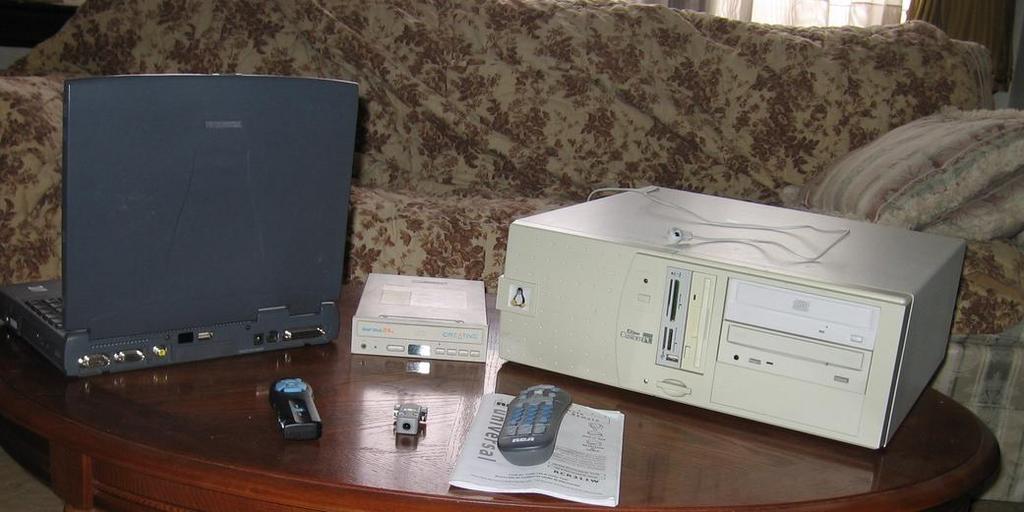
Here, I am going to demonstrate how to build a LIRC system. For hardware, you need an infrared receiver, which you might have already, and a remote control. A small number of PCs come with an infrared receiver that is supported by the LIRC software. Many laptops come with an IrDA standard interface for doing infrared networking and some IrDA interfaces, but not all of them work with LIRC. Many TV tuner cards come with an infrared port that is supported by LIRC. In addition, Creative Labs used to produce a series of CD-ROM drives that included an infrared port supported by LIRC. If you don't already have an infrared port for your PC, however, you need to look at other options, which I will get to shortly.
A small number of radio-based remote controls have been made to work with LIRC, but basically, LIRC is an infrared system. For remote controls, almost any "universal" infrared remote control can be made to work with LIRC. The only brand of remote control that is notorious for its problems and should be avoided is Bang & Olufsen.
Do give some thought as to how much control you want/need over your PC. For example, if you are planning to do presentations for which your control concerns amount to next/last slide, then a small remote you can carry in your pocket may take priority over a remote with a lot of buttons. If, on the other hand, you want to run a MythTV box, you probably want all of the functions of a TV, DVD player and so on, meaning more buttons. Thus, a larger remote is an acceptable trade-off. Either way, your options here are wide.
The price for the remote can range from effectively free if you have an old VCR remote up to a several hundred dollar color display screen remote that does almost everything (see the Logitech Harmony series of remote controls). With MythTV in mind, I got a factory refurbished RCA remote with batteries at an electronics clearance shop for less than five dollars.
Assuming you don't already have an infrared detector, you have to buy or build one. You can find plans for several infrared detectors on the LIRC Web site, including plans that use the serial port, a USB port or the parallel port. Here, I walk-through building the simple serial port detector inside a DB9 hood. This serial port design does not follow the RS-232 standard fully, but it is close enough for most desktop PCs. When it comes to laptop computers, which often don't fully follow the RS-232 standard themselves, this design may be problematic. The circuit diagram is laid out in Figure 1. In Figure 2, you can see one possible layout on perfboard.

Figure 1. Circuit Diagram

Figure 2. Perfboard Layout
To build your own detector, you need a few parts:
IC1 - SFH 5110-38 Infrared detector, or compatible
IC2 - 78L05 voltage regulator
D1 - 1N4148 diode
R1 - 4.7 K ohm 0.25 watt carbon resistor
C1 - 4.7 uF 16 volt electrolytic capacitor
DB9 female solder connector
DB9 hood
Miscellaneous: perfboard, hookup wire, rosin core solder, flux remover
You can expect that finding a suitable infrared detector will be something of a pain. The rest of the parts are quite common and easy to locate. The total cost for all of the above parts should be under $15.
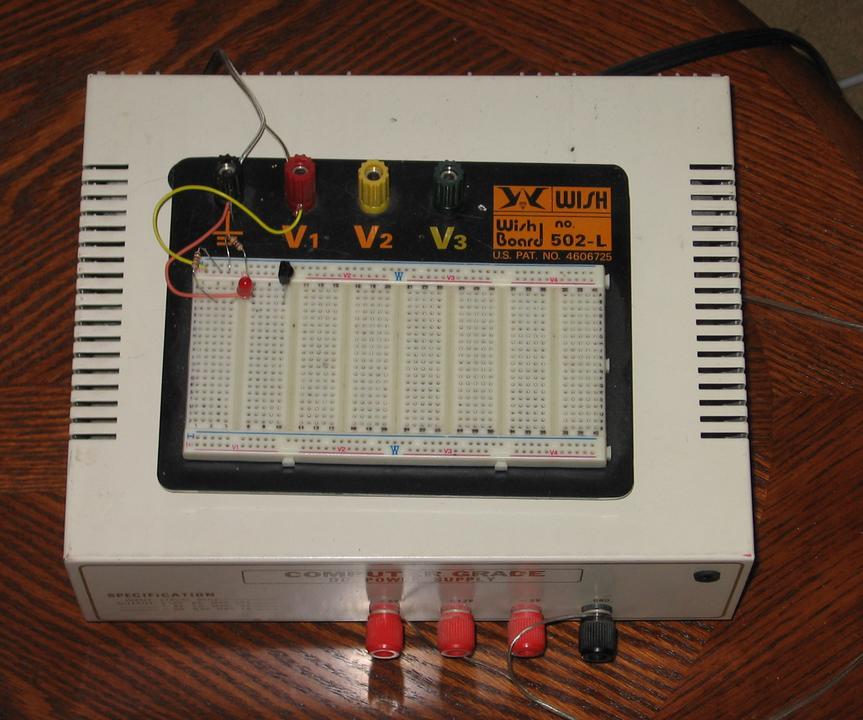
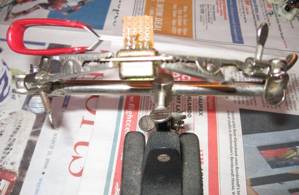
Testing the Mystery Infrared IC
In my case, I had some infrared detector ICs left over from a project I made several years ago. I no longer had the data sheets, however, and the markings on the ICs were not useful. So, I needed to be certain of the pin-outs. On my local user group mailing list, Peter L. Peres suggested setting up the circuit shown in Figure 3 on a prototyping board. The idea behind this is you can set up various possible connections with the voltages involved set so low that there is little chance the IC will be damaged. After setting up each combination, fire a known good infrared remote control at the sensor IC and see if the LED flickers. For the test setup, you ideally want a 5 mA red LED; otherwise, the flicker may be very faint. Regardless, you should do these tests in a dimly lit room.

Figure 3. Test Setup
The pin-outs for my mystery infrared detectors are the same as the Osram SFH-5110 series of detectors. The layout of that series assumes a SFH-5110 or compatible detector. This circuit can be made to work with dozens of detectors, but not all have the same connection layout, so do double check your own compatability.
In addition to the above parts, you need to have a few tools available:
Low wattage soldering iron (20-40 Watts)
Soldering iron stand
Wire cutter
Wire stripper
Small screwdriver
Small saw
Optional but recommended: clip-on heat sink, third-hand parts holder, solder remover tool
When it comes to soldering irons, 100 and 200 watt versions are available for people who do things such as make stained glass windows. The problem with these high-power soldering irons is they get very hot very fast, and computer parts can be destroyed with too much heat. Therefore, don't use a soldering iron with more than 40 watts, and I recommend using one closer to 25 watts. The "cold heat" soldering irons promoted on television have their place for some jobs, but that place isn't here. Among several problems they have, their tips are much too big for the sort of small-work precision this project requires.
Heat is an issue throughout this project. As noted, the parts in this project can be destroyed by too much heat, yet we need enough heat to melt solder. People with a lot of experience soldering could bond all of these parts together quickly enough that heat doesn't build up, so they could get away without using a heat sink. But as a hobbyist who solders only occasionally, I find that a clip-on heat sink buys a lot of leeway and saves a lot of parts from destruction.
Several Web sites are dedicated to explaining how to make good solder joints. I suggest referring to this one or this one.
Flux is a cleaner put into the middle of the solder to help ensure good solder connections. Two kinds of flux-containing solders are on the market, acid and rosin core solders. Acid core solder is designed for things such as radiator repairs; it should be avoided at all costs for electronic work.
Respect the things you are dealing with; if handled carelessly, the soldering iron can burn. Most solders sold in North America contain lead, a metal with known health issues, so you should try to limit your exposure to it. Flux remover typically contains alcohol, so don't use it near an open flame or other heat sources. Finally, the flux in the solder burns off as you work, creating tiny wisps of smoke. So work in a well-ventilated and well-lit area.
Do collect in advance the parts and tools you need for the project, as you see in Figure 2. Because I was doing my work at the kitchen table, I laid out some newspapers to protect the table surface.
It doesn't matter which way you install the resistor, but for all of the other parts, position matters. The capacitor has a minus sign beside one of the wires to identify which wire is which. The diode has a black line at one end to identify which end is which. When looked at from above, the 78L05 voltage regulator looks like a half moon, and where the wires are relative to the flat sides matters. There is a lens on one side of the infrared detector, and where the wires are relative to that lens counts. Numbers should be molded beside the pins on the DB9 connector.
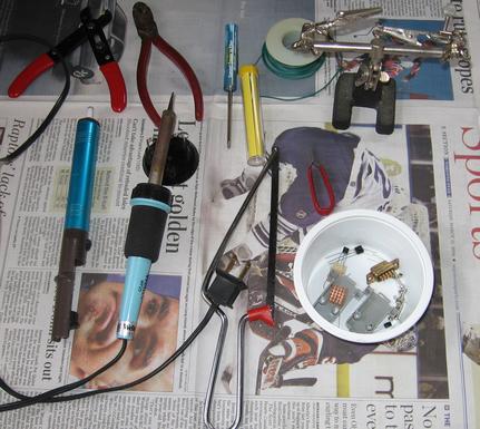
The Tools and Parts Laid Out for Building a Detector
Perforated board, or perfboard, is a wonder for hobbyist electronics work. It is a thin piece of non-conductive, heat tolerant plastic with holes drilled into it at 0.1" intervals. I use perfboard that has small copper rings bound to the board around each hole, which helps ensure the parts stay attached to the board.
The first step is to cut a piece of perfboard down to the right size. I used a small hacksaw for this job, but a Dremel or other small power-cutting tool can be used. We need a grid that is 4x5 holes, so cut along a line six holes in from one edge and five holes in from the other edge.
The first step is to attach the perfboard to the female DB9 connector. Place the board so that it is between the top and bottom row of pins and the copper rings are lined up with the solder cups for pins 6 through 9. Then, solder pins 6, 8 and 9 to the copper rings on the board.
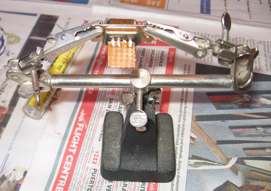
The Start of Construction with the Perfboard Attached to the DB9
You need to thread the wire from the end of the diode that does not have the black line on it through a hole (C1) in the perfboard and connect it to pin 7 in the DB9 connector. Trim the diode wire so it fits into the DB9 connector. When positioning the diode, remember that you don't have a lot of space above the perfboard, so keep everything close to the board. Clip the heat sink to the wire that goes into the diode and solder it into the DB9 connector. Wait a minute for things to cool down, and then solder the diode to hole C2. Run the wire from the black line end of the diode through hole D1, up to hole D2 and trim off the excess wire. Reposition the heat sink, solder hole D1 and then remove the heat sink.
The resistor goes in next. Place one end in hole D2 and the other in D3. Remember that you need to keep the resistor close to the board, but leave enough room for a wire to get into hole D4. The resistor has a high heat tolerance, so I skipped using the heat sink for this part. Position the resistor wire that comes in through hole D2 so that it ends by hole C2, and trim the excess. The resistor wire that goes into hole D3 should end by hole D4. Leave hole D3 alone for now, and solder hole D2.
Using a piece of wire trimmed from the diode, we make a little jumper. The wire needs to be bent so that one end goes into pin 5 of the DB9 connector, through hole B1 and then up, so it's just touching hole B4. Solder pin 5 in the DB9 connector and hole B1.
Now, put the voltage regulator into holes A2, A3 and A4. Remember to pay attention to the orientation of the regulator. Leave the wires on the component side long enough that you can clip in the heat sink and later fold the voltage regulator over, so it fits close to the board. Clip on the heat sink, solder holes A2, A3 and A4 and then remove the heat sink.
Part Way Through Construction with the Heat Sink in Place
The next part is the capacitor. Pay attention to which wire is negative, and leave enough space for the heat sink and to fold the capacitor over. Clip on the heat sink, solder holes A3 and B3 and remove the heat sink.
Our second jumper comes next, made from a short piece of hook-up wire about 0.75" (2 cm) long. Trim the insulation off both ends and solder one end into pin 1 of the DB9 connector. The other end goes to hole D4. It may be a tight fit, and you may need to shift the resistor to fit things, which is why the resistor wasn't soldered earlier. Once the jumper is in place, solder the resistor at hole D3.
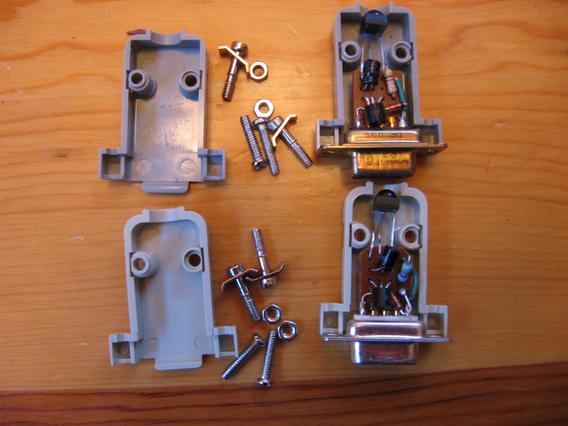
Two Almost-Complete Infrared Detectors
Finally, we come to the infrared sensor. You are going to have to do some test fittings to make sure that the leads are long enough so the sensor is just behind the hole in the plastic DB9 hood. This fitting also may require that you push the capacitor slightly to one side, out of the way. Once the length is adjusted, bend the wire that goes in though hole C4 so it goes across to hole D4. Clip on the heat-sink, solder holes A4, B4, C4 and D4 and remove the heat-sink.
Now you might want to take a minute to clean up. Apply some flux remover, per the manufacturer's instructions, to the solder side of the perfboard to clean away any flux residue left from the assembly.
The last construction job is to assemble the DB9 hood around the project. Once that's done, plug the interface into the serial port on your computer and start the machine. That finishes the hardware part of the project.
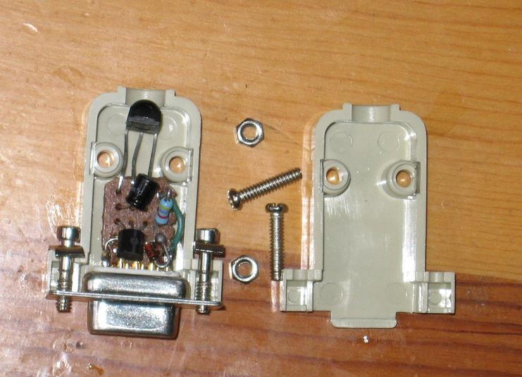
A Close-Up of a Completed Detector
I cheated a little for the software and used a short cut made possible by Jarod Wilson, who has done a great job of documenting MythTV and Fedora Core 4. After you have used up2date to bring your system up to date with the latest security patches, start up a terminal session and enter:
   su
   <enter the root password>
   echo "export KVER=\`uname -r\`" >>
/etc/profile.d/kver.sh
   cd /etc/yum.repos.d/
   wget http://wilsonet.com/mythtv/atrpms.repo
   wget http://wilsonet.com/mythtv/freshrpms.repo
   yum install lirc-kmdl-$KVER
   yum install lirc-lib
   wget --no-check-certificate
https://svn.wilsonet.com/svn/mythtvology/trunk/rc.sysinit-mm.diff

   patch /etc/rc.d/rc.sysinit < rc.sysinit-mm.diff
   yum install lirc
Assuming that you are connecting the detector to ttyS0, put the following lines in file /etc/modprobe.conf:
   install lirc_serial /bin/setserial /dev/ttyS0 uart
none ; /sbin/modprobe --ignore-install lirc_serial
   alias char-major-61 lirc_serial
   options lirc_serial irq=4 io=0x3f8
If you are connecting the detector to ttyS1, enter the following lines:
   install lirc_serial /bin/setserial /dev/ttyS1 uart
none ; /sbin/modprobe --ignore-install lirc_serial
   alias char-major-61 lirc_serial
   options lirc_serial irq=3 io=0x2f8
To test that you have a working infrared detector, type mode2. Point a working remote control at your detector and start pressing buttons. If you see something like:
   pulse 1187
   space 596
   pulse 598
   space 623
   pulse 553
   space 643
   pulse 630
   space 603
you have a working detector. If not, it's time to open up the hood and start troubleshooting. The first thing to check for is cold solder joints, where the solder has not bonded properly with the parts. Look for connections with a dull surface. Clip the heat sink to the appropriate nearby part, reheat those joints and remove the old solder with your solder remover. Then, re-solder using fresh solder.
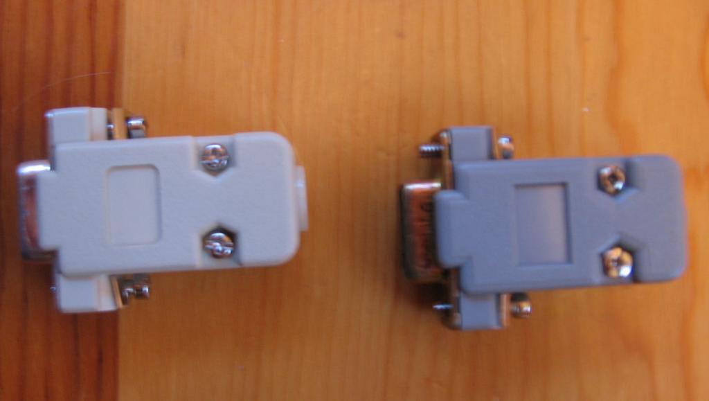
Two Fully Complete Detectors
Assuming things do work now, you need to start configuring your system to work with the remote. But that is another significant project, one for another article.
Colin McGregor works for a Toronto area charity, does consulting on the side and has served as President of the Toronto Free-Net. He also is secretary for and occasional guest speaker at the Greater Toronto Area Linux User Group meetings.
