
Porting LinuxBIOS to the AMD SC520
In this article, we describe the work done by the Cluster Research Team at Los Alamos National Laboratory to port LinuxBIOS to the AMD SC520 CPU. Although space does not permit a detailed description of all the work involved, we hope you can get some idea of what it takes to port to a new board.
The AMD SC520 is a small, low-power, integrated CPU. It is used in many embedded applications, one of the more interesting being the Portland Aerospace Society's open-source rocket. This rocket uses a standard board from Kontron to control all onboard computing functions. The board features a number of nice control buses, including the CAN bus for power control of rocket subsystems.
We were asked whether we could port LinuxBIOS to the board the rocket team uses. We purchased the board they use and found one main problem: the BIOS Flash is soldered on. If you burn a bad BIOS, the board is now a nice paperweight. It might be nice to have a fancy burned-out board as a paperweight, but we would rather have working boards.
After doing some research, we learned that Advanced Digital Logic (ADL) makes a nice SC520 board with a removable BIOS Flash part. We decided to use this board for development. We've used ADL boards for our miniclusters in the past, and they've worked well.
We would start our work by porting to the board with removable Flash. Once the port is solid, our plan was to take a deep breath and try it on the board with a non-removable Flash. If we fail, of course, we're the proud owners of a $400 brick!
The steps in any LinuxBIOS port process change little from board to board. First, enumerate the resources provided on the mainboard, such as the CPU, I/O parts and so on. Next, create the configuration files that describe the resources and populate the directory tree with those files. Then, fill in the blanks with code.
LinuxBIOS itself is about 98% C code. The small amount of assembly involved is common to almost all the boards for a given CPU. In this sense, LinuxBIOS is a far better piece of code than proprietary BIOSes, which we are told are almost completely assembly code. We have not seen this source code, of course.
The LinuxBIOS build process bears little resemblance to the Linux kernel build process. Instead, the LinuxBIOS build process was inspired by the Plan 9 and BSD kernel build processes, although the LinuxBIOS process adds more formality and control. A lot of checking is needed for building a BIOS, as the price of error is high. Because our clusters may have 1,024 or 2,048 nodes, we want to make sure that the BIOS we flash to all the nodes at once is good. As we will see, however, we can afford to flash a bad BIOS if we use LinuxBIOS's fallback BIOS feature.
A target is a specific instance of LinuxBIOS for a motherboard. As built for a target, a LinuxBIOS image consists of glue code for resource management code and the resource code itself. A resource can be thought of as one or more .c files that control a hardware component, be it a motherboard, CPU or other chip. Resource code can invoke code for other resources as part of the configuration process. For example, the motherboard resource invokes code for CPU startup.
Each resource has a directory, so for the SC520, we need to have a directory called src/cpu/amd/sc520. The directory includes source code and two configuration files, one of which specifies options used for the resource and default option values. The other specifies what parts are built and how they are built. A given configuration file for a resource may specify other resources to be used, in which case the configuration files for those resources are read in and processed.
The LinuxBIOS configuration tool, starting from an initial configuration file called the target configuration file, creates a build directory. Once the configuration tool is run, the user changes to the build directory and types make. At that point, an image of the LinuxBIOS for that target is built and can be burned into Flash.
A given motherboard can have several target configuration files. Different options may be set for these different targets. One target might have a lot of debugging, another might use a different bootloader and so on. All of this control is set by options in the build process.
Options are defined in the LinuxBIOS source tree, and only defined options may be used. Options have default values and can be set only once in order to avoid confusion in how they are set and what values they may have.
The goal of this process is to make it easy to build all the targets on a single machine, quickly, while having only one copy of the source. A second goal is to avoid errors that cropped up in earlier versions of LinuxBIOS, when options were uncontrolled or set in too many places. The process supports cross-compilation, so we can build our PowerPC targets on an x86 machine.
A portion of the LinuxBIOS directory tree structure is shown in Figure 1. Starting at the top of the tree, there are three main directories: src, targets and util. The src directory contains all the source for all the BIOSes—all mainboards, all CPUs, all devices and so on. You build a specific BIOS in the target directory using a config file. For example, for our project, we built our BIOS in the targets/digitallogic/msm586seg directory, using the file Config.lb in that directory. Finally, the util directory contains many utilities used to create BIOS files or to burn the BIOS image into the motherboard Flash part.
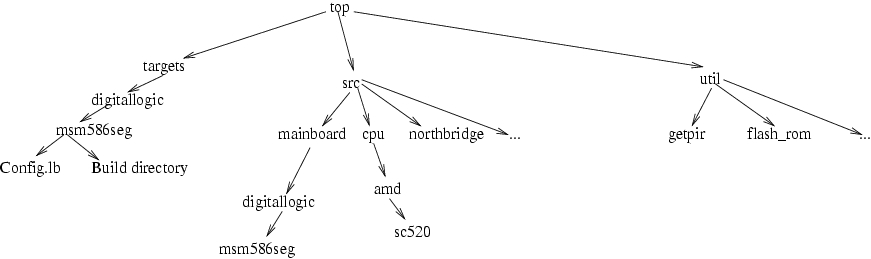
Figure 1. The LinuxBIOS directory tree includes three top-level directories for source, config files and utilities.
Configuration files in LinuxBIOS describe resources and how they are used in the construction of a target. Each resource can have a set of options defined for it. The set of all available options is defined in one file, src/config/Options.lb; only options defined in that file may be used or set in configuration files. Once a resource is named in a configuration file, resources defined within the scope of that resource inherit the options settings for that resource. The options have lexical scope; once the block for the resource ends, the options revert to values they had before the block was started. Options may have a default value set in the Options.lb file, or it may not be set; they may have a default value set in the mainboard configuration file; or they may be set in the target configuration file. To avoid the confusion we saw in earlier versions of the configuration tool, options may be set in only a few places: the target file, the mainboard file and CPU files. Options may be set only once. Thus, an option may have a default value, which can be changed once and only once in a configuration file. Forcing the set-once rule avoids problems we saw earlier with dueling configuration files.
A full writeup on the configuration language would consume this entire article. Therefore, this article touches on the important points, but we cannot cover all the aspects of the configuration language.
In all mainboards, some resource hardware can be queried to determine what other resources it needs, for example, how much memory and I/O space it needs. There also is hardware that cannot be queried, such as the wires that wire a PCI slot to an interrupt controller. For the latter type of resource, the only way to tell the BIOS about it is to put the information directly into the BIOS. Unfortunately, this information is contained in many places in PC BIOSes. Interrupt routing may be found in the $PIR (uniprocessor), _MP_ (multiprocessor or IO-APIC) or ACPI tables. The configuration tool must generate these tables, but the user in turn must tell the tool what values go in the tables.
Super I/O chips cannot be queried dynamically, and the location in I/O space and type of Super I/O chip must be specified in the mainboard configuration file.
Newer PC mainboards are harder to figure out at runtime. For example, Opteron processors have three HyperTransport ports that can be wired in arbitrary configurations on different mainboards. The configuration file for a mainboard has to specify how these ports are wired.
On modern systems, with Synchronous DRAM chips, the memory is not accessible until a lot of setup has been done. The size and parameters of the DRAM are read in over a two-wire bus called the SMBUS. Thus, in order to establish working memory, the BIOS has to:
Turn on the chipset to some extent.
Enable the SMBUS, usually on a Super I/O or southbridge.
Read in parameters of DRAM over SMBUS; more than 20 in some cases.
Perform complex calculations to determine timing.
Initialize DRAM control registers with proper values.
Perform a complex sequence of reads not writes from DRAM to get it running.
All this has to be done without a stack, which means that function calls and variables are almost impossible to use. Without memory, programming is limited to the registers. Function calls can be made only one level deep. In the bad old days, a big, bad ball of assembly code was used to get this work done. Expert assembly code writers used every trick in the book to get this code working. Writing this code is the single hardest part of any BIOS.
In 2002, Eric Biederman of Linux NetworX developed a compiler called romcc. romcc is a simple optimizing C compiler—one file, 25,043 lines of code—that uses only registers, not memory. The compiler can use extended register sets such as MMX, SSI or 3DNOW. romcc allowed us to junk almost all of the assembly code in LinuxBIOS, so that even the earliest code, run with no working DRAM, can be written in C.
romcc is used only for early, pre-memory code. For code that runs after memory comes up, we use GCC.
The build process builds a binary image that is loaded to a Flash part. LinuxBIOS provides a utility, flash_rom, for this purpose. Alternatively, you can use the MTD drivers in the Linux kernel.
The layout of a typical ROM image is shown in Figure 2. The top 16 bytes contain two jump vectors, a jump to the fallback and a jump to the normal. LinuxBIOS always jumps to the fallback first. If all is well, it jumps back to the jump to normal vector at the top of memory, and from there to the normal image. If the fallback code detects problems or if the CMOS settings indicate that fallback BIOS should be run, the fallback BIOS runs.
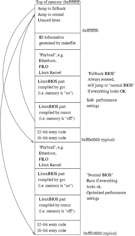
Figure 2. A typical ROM image includes a fallback BIOS to allow booting in case of trouble with the main BIOS.
Enough overview, let's get to work. To build support for a new board, we start with the mainboard first, and the easiest way to do this is to pick a similar mainboard. Because the Digital Logic ADL855 is much like the SC520, we start with that. We can clone much of the directory structure of the ADL855 for the SC520 board.
The basic naming process for directories in LinuxBIOS is to name the type of resource, in this case, mainboard; the vendor, here digitallogic; and the part name, in this case, msm586seg. Before we start the mainboard configuration file, we need to know what's on this mainboard. We don't have to get everything at first; in fact, we can leave a lot out simply to get something to work. Typically, the best approach is to make sure you know what drives the serial port and make sure you get that. To get DRAM up, you need to make sure you set up whatever device drives the SMBUS. None of these chips are in the right state when the board is turned on; you need to set a few bits to get things going.
For figuring this all out, you have a few choices. Almost always, the easiest thing to do is boot Linux and type lspci. For work with this type of board, it's easiest to have a CompactFlash part with a small Linux distribution installed so you can boot long enough to run the lspci command. You can use lspci to dump configuration space registers too, which sometimes is invaluable for discovering how to set control bits the vendor might have forgotten to tell you about. The setpci command also is handy for probing bits and learning the effects of setting and clearing them. On several boards, we've used setpci to probe the chipsets to find undocumented enable lines for onboard devices.
Although lspci shows discrete devices, on the SC520 they are integrated into the part. In the old days, we would create a new resource even if the part was integrated into the CPU. We have decided, based on previous experience, that if a part is integrated into the CPU, we do not consider it a separate resource. Therefore, there are no separate directories for the north and south bridge. The code for these devices is supported in the CPU device. The LinuxBIOS code base is flexible in this way. A given BIOS can be implemented with different types of parts, but in fact none of them are required.
Our first step in getting the resources set up for the mainboard is to name the CPU and set up the directory for it. The code for a given CPU is contained in the src/cpu directory. Luckily, the CPU in this case is an x86 system, so there is no need to add an architecture directory.
This article traces development from our point of view—a LinuxBIOS developer. If you want to develop a new tree, however, you can clone the LinuxBIOS arch repository, do development and submit patches to a developer. We will check your patches and help get them into the repository. In most cases with new developers, if their code is good, we allow them to become developers for our team.
We create a directory, src/cpu/amd/sc520, and populate it with files to support the CPU. We are not going to show all the commands for everything we do in this port, but for this first change, we show the commands to give you flavor of how it works. Even this simple part explains a lot of the important aspects of how LinuxBIOS is constructed:
cd src/cpu/amd
mkdir sc520
tla commit
This sets up the directory; now we need to populate it. The src/amd/socket_754 directory is a good candidate for providing model files, so we use them:
cd sc520
cp ../socket_754/* .
This gives us an initial set of files:
rminnich@q:~/src/freebios2/src/cpu/amd/sc520> ls
chip.h Config.lb socket_754.c
The chip.h file defines a simple data structure that is linked into the BIOS image by the Makefile, which is generated by the config tool. For this part, it's basically empty:
rminnich@q:~/src/freebios2/src/cpu/amd/sc520> catchip.h

extern struct chip_operations cpu_amd_socket_754_ops;

struct cpu_amd_socket_754_config {

};
What does this mean? First, we create an instance of a struct called chip_operations for this part, called cpu_amd_socket_754_ops. This is a generic structure, used by all chips. This generic structure looks like this:
/* Chip operations */

struct chip_operations {

        void (*enable_dev)(struct device *dev);

#if CONFIG_CHIP_NAME == 1

        char *name;

#endif

};
The chip_operations structure, in src/include/device/device.h, defines a generic method of accessing chips. It currently has two structure members: a function pointer to enable the device, enable_dev; and an optional name, used for debug prints, called name. Notice that in the style of the Linux kernel, C preprocessor-enabled code is controlled by testing the value of a preprocessor symbol, not by testing whether it is defined. As you can see, the enable_dev function takes a pointer to a device struct.
Why do we do this? Although there is one chip_operations structure for a type of chip, there is a device structure for each possible instance of a chip. We say possible because a device structure is defined for each chip that may exist in a system. Consider an SMP motherboard, which has from one to four or even eight CPUs; not all the CPUs may be there. Part of the job of the enable function is to determine whether the chip is even there.
The device struct looks like this:
struct device {
   struct bus * bus; /* bus this device is on, for
                      * bridge devices, it is the
                      * upstream bus */

   device_t sibling; /* next device on this bus */
   device_t next;    /* chain of all devices */
   struct device_path path;
   unsigned vendor;
   unsigned device;
   unsigned int class; /* 3 bytes:
                        * (base,sub,prog-if) */
   unsigned int hdr_type; /* PCI header type */
   unsigned int enabled : 1; /* set if we should
                              * enable the device */
   unsigned int initialized : 1;
    /* set if we have initialized the device */
   unsigned int have_resources : 1;
    /* Set if we have read the device's resources */
   unsigned int on_mainboard : 1;
   unsigned long rom_address;
   uint8_t command;

   /* Base registers for this device. I/O, MEM and
      Expansion ROM */

   struct resource resource[MAX_RESOURCES];
   unsigned int resources;

   /* links are (downstream) buses attached to the
    * device, usually a leaf device with no child
    * has 0 busses attached and a bridge has 1 bus */

   struct bus link[MAX_LINKS];

   /* number of buses attached to the device */
unsigned int links;

   struct device_operations *ops;
   struct chip_operations *chip_ops;
   void *chip_info;

};
This is a pretty complicated structure, and we don't go into all the issues here. During the configuration step, the LinuxBIOS configuration tool instantiates a struct device for each chip by writing C code to a file in the build directory. The C code that the config tool generates has initial values so that the array of device structures forms a tree, with sibling and child nodes. The LinuxBIOS hardwaremain() function walks this tree, starting at the root, and performs device probing and initialization.
The last structure member is a void *—that is, a pointer that can point to anything. The next-to-last element is a chip_operations pointer. As part of the creation of the initialized C structures, the config tool fills in the chip_info and chip_operations pointer with a pointer to the per-chip configuration structure and per-chip-type structure. Thus, each device in the tree has pointers to structures for the type of chip and the individual instance of the chip. The enable structure member, which is a function pointer, for the type of chip is called with a pointer to the structure for the device for each instance of the chip. The device structure has a lot of generic structure members, as you can see, and it has a pointer to a structure for nongeneric chip components.
For each chip, we optionally can provide declarations of both structures, but it is not required. The chip_operations structure, or the type-of-chip structure, has a type fixed by LinuxBIOS itself; the chip_info structure has a structure fixed by the chip. The enable function in the chip_operations structure can be un-initialized, in which case there is no enable function to call for the chip—the chip is always enabled. That is the case for the SC520 CPU—there is only one, and it is always there.
Now we need to change these files to match the SC520. We show them before and after to give you an idea how it looks.
chip.h changes to look like this:
extern struct chip_operations cpu_amd_sc520_ops;

struct cpu_amd_sc520_config {

};
The enable_dev pointer is empty and is not called. We leave it empty for now but may fill it in later as needed. Similarly, there are no special structure members for the chip_info structure.
The C code looks like this:
#include <device/device.h>
#include "chip.h"

struct chip_operations cpu_amd_socket_754_ops =
  { CHIP_NAME("socket 754") };
The changes are simple; we rename the file to sc520.c and then change it to this:
#include <device/device.h>
#include "chip.h"

struct chip_operations cpu_amd_sc520_ops =
  { CHIP_NAME("AMD SC520") };
The final file is the Config.lb file. Here we get our first glance at what a configuration file looks like. The original file looks like this:
uses CONFIG_CHIP_NAME

if CONFIG_CHIP_NAME

        config chip.h

end

object socket_754.o

dir /cpu/amd/model_fxx
The first line declares that we are using the CONFIG_CHIP_NAME option. The language requires that we declare the variables we are going to use before we use them. In the case of this file that seems trivial, but in longer files this requirement is really useful. Second, if we are using the CONFIG_CHIP_NAME option, we use the chip.h file. Notice that nothing is set in chip.h unless we were using the CHIP_NAME macro, which is why this test is there. We declare any object files produced in this directory, in this case, socket_754. Finally, we include another directory using the dir keyword. The naming scheme in the config language for other directories is that the pathname is relative if it does not start with a /. Otherwise, it is rooted at the source of the LinuxBIOS source tree. In this case, the dir directive points to src/cpu/amd/model_fxx. As it happens, this is code for Opteron and is of no use to the SC520. After modifying this file for the SC520, it looks like this:
uses CONFIG_CHIP_NAME

if CONFIG_CHIP_NAME

        config chip.h

end

object sc520.o
That's about it. We've now set up support for the SC520.
Now we set up the mainboard. We first cd to mainboard/digitallogic and issue:
mkdir msm586seg
We then populate it from the adjacent adl855pc directory.
There are a lot of files here. We do not have enough space here to go into the changes for each file, but we can summarize what we do to each one.
This file is compiled by romcc, and in a proprietary BIOS it would be a large blob of assembly code. To start, we completely empty this file—all it should have is a print function. This is the easiest way to get a new port going—make sure you have the ability to get some output. There is not room to show the whole file, but you can see it in the repository or use viewarch. There are two key things to get right, however. First is picking include files. For romcc, additional C code is not linked in; it is included. The include files look like this:
#define ASSEMBLY 1

#define ASM_CONSOLE_LOGLEVEL 8

#include <stdint.h>
#include <device/pci_def.h>
#include <arch/io.h>
#include <device/pnp_def.h>
#include <arch/romcc_io.h>
#include <arch/hlt.h>
#include "pc80/mc146818rtc_early.c"
#include "pc80/serial.c"
#include "arch/i386/lib/console.c"
#include "ram/ramtest.c"
#include "cpu/x86/mtrr/earlymtrr.c"
#include "cpu/x86/bist.h"
#include "cpu/amd/sc520/raminit.c"
For romcc, we define the ASSEMBLY value to 1. We also set the console log level for assembly to a very high level—8 in this case. LinuxBIOS uses macros for printing so that when a production BIOS is built, the debug print macros can be compiled out to save space. A console log level of 8 ensures that every print call is compiled.
Here's the main function, which does nothing at all:
static void main(unsigned long bist)

{
    print_err("Hello\n");
}
With this simple main we can test a lot. We can build the BIOS, load it and see if we get a printout. Simply getting print to work is a huge step in getting your BIOS going.
We saw chip.h for a CPU; is it different for the mainboard? In fact, it's not really different at all:
extern struct chip_operations
    mainboard_digitallogic_msm586seg_ops;

struct mainboard_digitallogic_msm586seg_config {
};
As before, there is a generic chip_operations structure and a specialized structure for the chip, which in this case is a mainboard. Every single device in LinuxBIOS is treated the same way. This uniform structure has proven to be powerful.
cmos.layout defines the structure of the CMOS memory, which is a battery-backed memory on the motherboard. We leave this unchanged for now.
Config.lb is pretty standard across platforms, so for reasons of space we show only a subset here, the part that is mainboard-specific. We are going to touch on a few highlights, but for more detail you need to study the full file in the archive.
This statement declares a driver file, mainboard.o, which is included in the set of binaries linked in to the final image:
##
## Build our 16 bit and 32 bit linuxBIOS entry code
##

mainboardinit cpu/x86/16bit/entry16.inc
mainboardinit cpu/x86/32bit/entry32.inc
ldscript /cpu/x86/16bit/entry16.lds
ldscript /cpu/x86/32bit/entry32.lds
These commands relate to early initialization. The config tool builds a loader script for the BIOS, an assembly code file as well as a C file and Makefiles. The mainboardinit command tells the config tool to add the entry16.inc and entry32.inc assembly code files to the assembly code file for the mainboard. The .lds files are used in the ld script to determine how the assembly code is linked.
A number of mainboardinit and ldscript directives are in this file. These are architecture-related, for example, for the x86 architecture; CPU-related, for example, specific to the SC520 CPU; and, in some cases, mainboard-related.
Now we come to the complicated part of the file, which we are going to simplify for reasons of space:
chip cpu/amd/sc520
     device pci_domain 0 on
          device pci 0.0 on end
          device pci 1.0 on end
   end
end
We are declaring the CPU and the nested devices under that CPU. The first device is the PCI domain, domain 0, which is the only domain this CPU has. We declare device 0:0.0 and 0:0.1. That's it for now—this does get more complex later, however.
Some of these files are complex, in some cases running to 100 or more lines, as some boards are complicated.
Failover.c is included in auto.c and is code for managing failover of the fallback BIOS image if the normal BIOS image is corrupted in some way.
PC hardware does not have a defined way of mapping PCI slot interrupt lines to interrupt pins on the interrupt controller. There is a structure in the BIOS called the $PIR structure that the operating system reads to find out how to map interrupts.
The irq_tables.c file has an initialized C structure that defines the connection of the interrupt lines. This structure is compiled into LinuxBIOS and forms the $PIR table.
This file is generated automatically by a utility provided with linuxbios, called getpir. It is found in util/getpir. You run this utility under Linux, when booted under the factory BIOS. The utility prints out the $PIR table as C code. One caveat: we have found that the $PIR tables on many BIOSes have errors. On occasion, we have had to fix the tables to correspond to the actual hardware.
This code is compiled by GCC, not romcc. There is not much to this file right now:
#include <console/console.h>
#include <device/device.h>
#include <device/pci.h>
#include <device/pci_ids.h>
#include <device/pci_ops.h>
#include "chip.h"

struct chip_operations
mainboard_digitallogic_msm586seg_ops = {
  CHIP_NAME("Digital Logic MSM586SEG mainboard ")

};
This file contains the names of options used for this mainboard. First, all the options to be used are listed, for example:
uses HAVE_FALLBACK_BOOT
If the option has some desired value, it may be set in this file:
## Build code for the fallback boot
default HAVE_FALLBACK_BOOT=1
which sets the option to 1. This option may be overridden in the target file; that is, we can set the following in targets/digitallogic/msm586seg/Config.lb:
option HAVE_FALLBACK_BOOT=1
and the BIOS can be built without a fallback boot image. In general, the default values set in this file do not need to be changed.
We do need to change the default ROM size, as it is set to 1024*1024 for the other mainboard:
default ROM_SIZE = 256*1024
Why make this a default? So that a target with a larger ROM size can override it. If you build a target for a 1MB of ROM, you would put the command:
option ROM_SIZE = 256*1024
Now we add the target directory for the mainboard:
cd targets/digitallogic
mkdir msm586seg
tla add msm586seg
cp adl855pc/Config.lb msm586seg/
tla add Config.lb
We then commit, and the code is in. Next, we fix up the Config.lb for the msm586seg:
target msm586seg
mainboard digitallogic/msm586seg
option DEFAULT_CONSOLE_LOGLEVEL=10
option MAXIMUM_CONSOLE_LOGLEVEL=10
romimage "normal"
        option USE_FALLBACK_IMAGE=0
        option ROM_IMAGE_SIZE=0x10000
        option LINUXBIOS_EXTRA_VERSION=".0Normal"
        payload /etc/hosts
end

romimage "fallback"
        option USE_FALLBACK_IMAGE=1
        option ROM_IMAGE_SIZE=0x10000
        option LINUXBIOS_EXTRA_VERSION=".0Fallback"
        payload /etc/hosts

end

buildrom ./linuxbios.rom ROM_SIZE "normal" "fallback"
The file defines seven basic things:
The target build directory is msm586seg; it could be anything.
The mainboard is the digitallogic/msm586seg.
The default console log level is 10; this controls which compiled-in messages are printed. It can be overridden by the CMOS setting in the normal BIOS image.
The maximum console log level is 10; this controls which print macros are compiled.
The normal romimage is not a fallback image; it is 0x10000 bytes (64KB), has a version tag of .0Normal and has a payload of /etc/hosts.
The fallback romimage is a fallback image; it is 0x10000 bytes (64KB), has a version tag of .0Fallback and has a payload of /etc/hosts.
The ROM target is linuxbios.rom; it has a size of ROM_SIZE, as defined in the mainboard Options.lb above, and has two images in it, normal and fallback.
Well, let's see how it goes. We have a script for this part, to save some typing:
cd src/targets

./buildtarget digitallogic/msm586seg
This step works. It builds, but we get errors, which is expected. The version covered above, by the way, is:
linuxbios@linuxbios.org--devel/freebios--devel--2.0--patch-21
if you want to see what goes wrong. With a few modifications, we get a working version, which is stored at:
linuxbios@linuxbios.org--devel/freebios--devel--2.0--patch-22
It builds! The next step is to see if we can get any serial output. Make sure, of course, that you place the Flash part you want to burn into the Flash socket or you're going to be pretty unhappy. Better yet, before you start burning, make a backup of your factory BIOS to cover for mistakes:
flash_rom -r /tmp/backup
Put in a new Flash part:
flash_rom /tmp/backup
and store the Flash part somewhere safe.
We're building on a laptop and using an SC520 running Linux as the burner node. So use:
scp linuxbios.rom root@burnnode:
ssh root@burnnode flash_rom linuxbios.rom
Let's find out if it worked. Be sure to follow our progress on the Linux Journal Web site.
You can track our progress on the Web page or the LinuxBIOS Wiki (see the on-line Resources)—we have set up a status page there so you can see how it is going.
We have tried to show you a quick overview of how to do a LinuxBIOS port to a new system. If you really want to give it a go, join the mailing list and tell people what you are doing. There's a lot of expertise out there, and people are ready to help. For the record, it took one person totally unfamiliar with this system four hours to build a new BIOS port from scratch. That's not bad. Although it looks rather complex, once you see how to build a BIOS, you probably will find it to be pretty easy.
This research was funded in part by the Mathematical Information and Computer Sciences (MICS) Program of the DOE Office of Science and the Los Alamos Computer Science Institute (ASCI Institutes). Los Alamos National Laboratory is operated by the University of California for the National Nuclear Security Administration of the United States Department of Energy under contract W-7405-ENG-36. Los Alamos, NM 87545 LANL LA-UR-05-3336.
How to Set Up a LinuxBIOS Port System
We do not use Flash part burners at LANL, and most other places also do not. To burn a new Flash part, we actually pop the Flash part out of a running machine, put in a new part and run the flash_rom program to erase and rewrite the part. By far, the easiest way to set up a LinuxBIOS port station is to have one machine on which to build, one machine on which to burn and one machine on which to test.
The worst case is to have the burn, build and test machine be one and the same. In other words, the user has to boot the machine, build the LinuxBIOS, pop the Flash BIOS part out and put in a test part, burn it, reboot the machine to test and, in the likely event of failure—this is a new port, after all—put the factory BIOS back in and boot. The edit/compile/test cycle time can be long, as long as 3–5 minutes. In some cases, the burn and build machine can be the same.
For the SC520, we had a build machine, our x24 laptop; a burn machine, which is an MSM586SEG board; and a test machine, another MSM586SEG board. To simplify the situation further, we ran the two MSM586SEG boards as two bproc slave nodes using the Clustermatic software suite. Clustermatic lets us set up the two slave nodes with no local disk of any kind. All the state and control is managed from the laptop. We have been doing ports this way for five years now, and it is the easiest possible way we have found.
We've made a 64MB compact Flash image available at the LinuxBIOS Wiki, so you can make a slave machine with no effort. For more details, see the Clustermatic Web site for instructions on how to set up a laptop as a master node.
Resources for this article: /article/8327.
Ron Minnich is the team leader of the Cluster Research Team at Los Alamos National Laboratory. He has worked in cluster computing for longer than he would like to think about.
