
Listening to FM Radio in Software, Step by Step
My article “GNU Radio: Tools for Exploring the Radio Frequency Spectrum” [LJ, June 2004] provides an overview of how the GNU Radio system works and discusses a couple hardware options for getting the RF signals digitized and into the computer. This article takes a look at how to use GNU Radio to listen to FM radio.
The hardware setup used in this article is shown in Figure 1. It's the brute-force, no-frills approach and is good for explaining how everything works. Later in the article, we discuss the Universal Software Radio Peripheral (USRP) and what it can do for you.
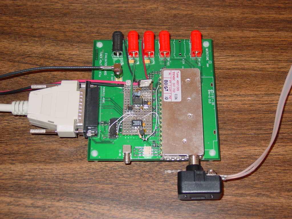
Figure 1. Cable Modem Tuner RF Front End
Our setup consists of a conventional FM dipole antenna, a cable modem tuner module mounted on an evaluation board and a 20M sample/second PCI analog-to-digital converter (ADC) card. The antenna plugs in to the input of the tuner module. The tuner module IF output is connected with a piece of coaxial cable to the ADC input on the back of the computer. The tuner module eval board is connected to the PC's parallel port so that we have a way of controlling the module.
The specific hardware we're using is a Microtune 4937 DI5 3X7702 cable modem tuner module and a Measurement Computing PCI-DAS 4020/12 ADC board. This particular tuner module is hard to get, but others, such as those from Sharp Microelectronics, ought to work fine (see the on-line Resources section).
The cable modem tuner functions as our RF front end and is responsible for translating the radio frequency signals that we're interested in down to a range that our ADC can deal with. In this case, the module translates a selectable 6MHz chunk of the spectrum in the range of 50MHz–800MHz down to a 6MHz chunk centered at 5.75MHz. For more background on these concepts, see the June article mentioned previously.
First off, let's take a look at what happens when we tune our front end to the middle of the FM band, say 100.1MHz. Figure 2 shows the received samples vs. time. This view, the time domain, is what you'd see on an oscilloscope. It's not particularly enlightening, but it does show that our samples are in the range of –170 to –70, which is fine. In an ideal world, they would be symmetric about zero. For our purposes, the offset won't matter.

Figure 2. ADC Samples in the Time Domain
The frequency domain provides additional information. In this case, we grab 1,024 samples at a time and compute the discrete Fourier transform using the fast Fourier transform (FFT) algorithm. This gives us a representation of the frequencies that are contained in the input signal. Figure 3 shows the resulting spectrum. The x-axis is frequency, and the y-axis is power in decibels (10 * log10 power). The low end is at zero Hz, and the top end is at 10MHz, half our sampling rate.
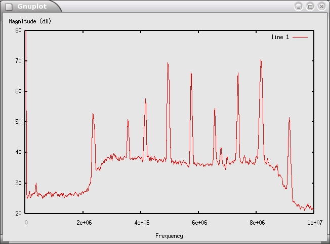
Figure 3. Fast Fourier Transform of FM Band with Nine Stations
Each of the spikes in Figure 3 is a radio station. Our software sees them all at once! To listen to a station, we need a way to separate it from all of the others, translate it to baseband (DC, 0Hz) and reverse the effect of the frequency modulation. We work through this step by step, but first let's talk about FM.
To understand how an FM receiver works, it's helpful to know a bit about how FM signals are generated. With FM, the instantaneous frequency of the transmitted waveform is varied as a function of the input signal. Figure 4 shows m(t), the input signal (the message, music and so forth), and s(t), the resulting modulated output. To be rigorous, the instantaneous frequency at any time is given by the following formula:
f(t) = k*m(t) + fc
m(t) is the input signal, k is a constant that controls the frequency sensitivity and fc is the frequency of the carrier (for example, 100.1MHz). Remember that frequency has units of radians per second. As a result, frequency can be thought of as the rate at which something is rotating. If we integrate frequency, we get phase, or angle. Conversely, differentiating phase with respect to time gives frequency. These are the key insights we use to build the receiver.
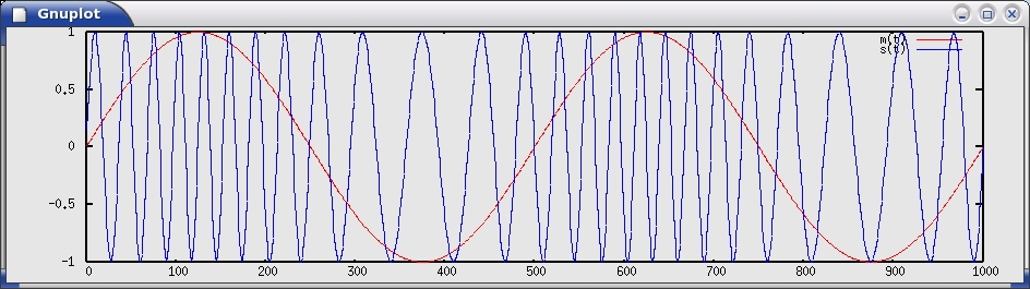
Figure 4. A Simple Frequency Modulated Signal
Figure 5 shows our strategy for listening to an FM station. If we remove the carrier, we're left with a baseband signal that has an instantaneous frequency proportional to the original message m(t). Thus, our challenge is to find a way to remove the carrier and compute the instantaneous frequency.
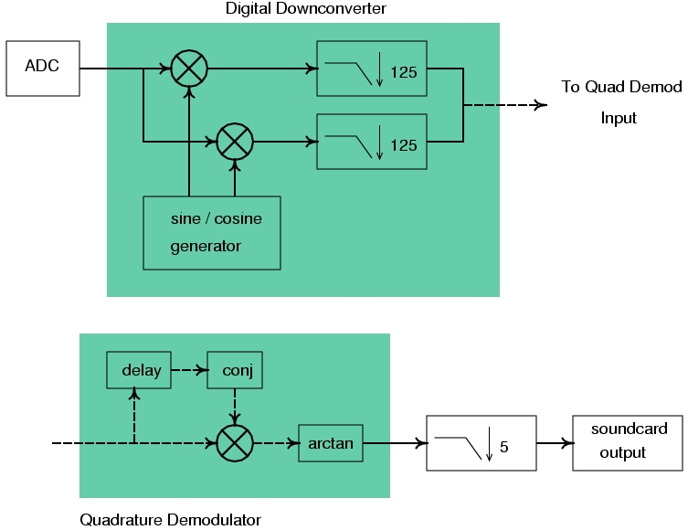
Figure 5. Block Diagram of FM Receiver
The first part is easy. We get rid of the carrier by using our software digital downconverter (DDC) block, freq_xlating_fir_filter_scf. This block is composed conceptually of a numerically controlled oscillator that generates sine and cosine waveforms at the frequency that we want to translate to zero, a mixer (that's a multiplier to us software folks) and a decimating finite impulse response filter. The scf suffix indicates that this block takes a stream of shorts on its input, produces a stream of complexes on its output and uses floating-point taps to specify the filter.
The digital downconverter does its job by taking advantage of a trigonometric identity that says when you multiply two sinusoids of frequency f1 and f2 together, the result is composed of two new sinusoids, one at f1+f2 and the other at f1–f2. In our case, we multiply the incoming signal by the frequency of the carrier. The output consists of two components, one at 2x the carrier and one at zero. We get rid of the 2x component with a low-pass filter, leaving us the baseband signal.
A straightforward implementation of the digital downconverter block in software is extremely expensive computationally. We'd be performing the sine and cosine generation and multiplication at the full input rate. On a Pentium 4, computing sine and cosine takes on the order of 150 cycles. Given a 20M sample/sec input stream, we'd be burning up 20e6 * 150 = 3e9 cycles/sec merely computing sine and cosine! Definitely a non-starter.
The good news is there's a better way to implement the DDC in software. This technique, described by Vanu Bose, et al., in “Virtual Radios” (see Resources), allows us to run all of the computation at the decimated rate by rearranging the order of the operations and using frequency-specific complex filter coefficients instead of real coefficients. The end result is a big win! We can do it in real time!
The next job is to compute the instantaneous frequency of the baseband signal. We use the quadrature_demod_cf block for this. We approximate differentiating the phase by determining the angle between adjacent samples. Recall that the downconverter block produces complex numbers on its output. Using a bit more trigonometry, we can determine the angle between two subsequent samples by multiplying one by the complex conjugate of the other and then taking the arc tangent of the product. Listings 1 and 2 show the implementation of the quadrature_demod_cf block. Once you know what you want, it doesn't take much code. The bulk of the signal processing is the three-line loop in sync_work.
Listing 1. Quadrature Demodulator Header
/*
 * Copyright 2004 Free Software Foundation, Inc.
 *
 * This file is part of GNU Radio
 *
 * GNU Radio is free software; you can redistribute
 * it and/or modify it under the terms of the GNU
 * General Public License as published by the Free
 * Software Foundation; either version 2, or (at
 * your option) any later version.
 */

#ifndef INCLUDED_GR_QUADRATURE_DEMOD_CF_H
#define INCLUDED_GR_QUADRATURE_DEMOD_CF_H

#include <gr_sync_block.h>

class gr_quadrature_demod_cf;
typedef boost::shared_ptr<gr_quadrature_demod_cf>
  gr_quadrature_demod_cf_sptr;

gr_quadrature_demod_cf_sptr
gr_make_quadrature_demod_cf (float gain);

/*
 * quadrature demodulator: complex in, float out
 */
class gr_quadrature_demod_cf : public gr_sync_block
{
  friend gr_quadrature_demod_cf_sptr
    gr_make_quadrature_demod_cf (float gain);
  gr_quadrature_demod_cf (float gain);

  float         d_gain;

 public:

  int sync_work (
        int noutput_items,
        gr_vector_const_void_star &input_items,
        gr_vector_void_star &output_items);
};

#endif /* INCLUDED_GR_QUADRATURE_DEMOD_CF_H */
Listing 2. Quadrature Demodulator Implementation
/*
 * Copyright 2004 Free Software Foundation, Inc.
 *
 * This file is part of GNU Radio
 *
 * GNU Radio is free software; you can redistribute
 * it and/or modify it under the terms of the GNU
 * General Public License as published by the Free
 * Software Foundation; either version 2, or (at
 * your option) any later version.
 */
#ifdef HAVE_CONFIG_H
#include "config.h"
#endif

#include <gr_quadrature_demod_cf.h>
#include <gr_io_signature.h>

gr_quadrature_demod_cf::gr_quadrature_demod_cf (
                                         float gain)
  : gr_sync_block (
       "quadrature_demod_cf",
      gr_make_io_signature(1,1,sizeof (gr_complex)),
      gr_make_io_signature(1,1,sizeof (float))),
    d_gain (gain)
{
  set_history (2);    // provide 1 sample look ahead
}

gr_quadrature_demod_cf_sptr
gr_make_quadrature_demod_cf (float gain)
{
  return gr_quadrature_demod_cf_sptr (
      new gr_quadrature_demod_cf (gain));
}

int
gr_quadrature_demod_cf::sync_work (
    int noutput_items,
    gr_vector_const_void_star &input_items,
    gr_vector_void_star &output_items)
{
  gr_complex *in = (gr_complex *) input_items[0];
  float *out = (float *) output_items[0];
  in++;         // ensure that in[-1] is valid

  for (int i = 0; i < noutput_items; i++){
    gr_complex product = in[i] * conj (in[i-1]);
    out[i] = d_gain * arg (product);
  }

  return noutput_items;
}
Tying this all together, Figure 6 shows the output of the digital downconverter, and Figure 7 shows the output of the quadrature demodulator. In Figure 7, you can see all the components of the FM waveform. From 0 to about 16kHz is the left plus right (L+R) audio. The peak at 19kHz is the stereo pilot tone. The left minus right (L-R) stereo information is centered at 2x the pilot (38kHz) and is AM-modulated on top of the FM. Additional subcarriers are sometimes found in the region of 57kHz–96kHz.

Figure 6. FFT at Output of Digital Downconverter
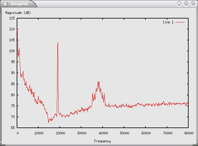
Figure 7. FFT of Demodulated FM Signal
To keep life simple, we low pass the output of the quadrature demodulator with a cutoff frequency of 16kHz. This gives us a monaural output that we connect to the sound card outputs.
Listing 3, available from the Linux Journal FTP site (see Resources), is the Python code that implements the overall receiver. In fact, it can listen to two FM stations at the same time, one out the left speaker and one out the right! I'm not arguing that this is a particularly practical application, but it does illustrate some of the power of software radio. This idea of extracting multiple stations concurrently could be used as the basis of a multichannel TiVo-like device for radio.
The code is split into three functions. main handles the argument parsing, manages the RF front end and controls the main signal processing loop. If we're receiving a single station, we tell the RF front end to put the station right at the center of the tuner's output frequency, the IF. If we're receiving two stations, we ensure that they're within 5.5MHz of each other. This restriction is due to the SAW filter built in to the cable modem tuner. It's a bandpass filter centered at 5.75MHz that's about 6MHz wide, the width of a North American TV channel. In this case, we split the difference and tune the front end exactly halfway between the two stations. build_graph instantiates the common signal processing blocks and connects them together. In both the single and dual-station modes, we use a single high-speed analog-to-digital converter for input and a single sound card for output. For each station that we want to receive concurrently, we instantiate a digital downconverter, quadrature demodulator and low-pass filter.
The maximum number of stations that can be received concurrently is a function of the speed of your computer. Even with our fancy implementation, most of the CPU cycles still are burned in the freq_xlating_fir_filter blocks. What we've described could be called the dumb ADC/brute-force method. One way to free up computational resources is to move the digital downconversion into hardware. Companies such as Texas Instruments, Intersil and Analog Devices sell dedicated ASICs that do this. The strategy used in the Universal Software Radio Peripheral (USRP) is to code the digital downconverter in the Verilog hardware description language and then download the resulting bitstream over the USB into the FPGA. This gives us a combined hardware/software system that maximizes flexibility while still allowing us to off-load some of the more computationally intensive parts into hardware. For more information on the USRP, see the GNU Radio Wiki.
We've walked through a fully functional but stripped-down multichannel FM receiver. We managed to turn a couple thousand dollars' worth of hardware into the equivalent of two $5 transistor radios, and we learned a bunch in the process. For those of you interested in pursuing FM listening, the GNU Radio code base includes a substantially higher fidelity FM receiver (hifi_fm.py), along with all kinds of other goodies.
Right now, a lot of interesting work is being done with GNU Radio. Some are focusing on mobile ad hoc networking, others on the legacy amateur radio waveforms, some on software GPS and another group is working on designing the next-generation ground-to-space amateur satellite communication system. Although the GNU Radio toolkit is mostly indifferent to I/O devices, most of these efforts are using or planning on using the USRP as the interface between the RF world and the PC.
Resources for this article: /article/7650.
Eric Blossom is the founder of the GNU Radio Project. Prior to his involvement with software radio, he spent many years in the secure phone business. When he's not hacking software radio, you're likely to find him practicing yoga or jujutsu. He can be reached at eb@comsec.com.
