
Debug and Squeeze Your PLIP Connection
PLIP (Parallel Line Internet Protocol) is simply a protocol to link two computers point to point through a PC parallel port, through which it exchanges IP datagrams. It is not a standard protocol; you will hardly find it outside the Linux operating system or covered in books about networking. It uses, however, a widely available cheap cable commonly known as a Laplink cable or a null printer cable. It provides a full network connection between two computers and, through routing, allows access to and from the rest of the computers, if the two linked computers are on a more complex network. Figure 1 shows a screen capture on a laptop where the window with the TV image comes through a PLIP interface from xawtv running on another PC with video4linux; not very practical, since the images took around 30 seconds to refresh (I must add that I substituted the original tobacco advertisement).
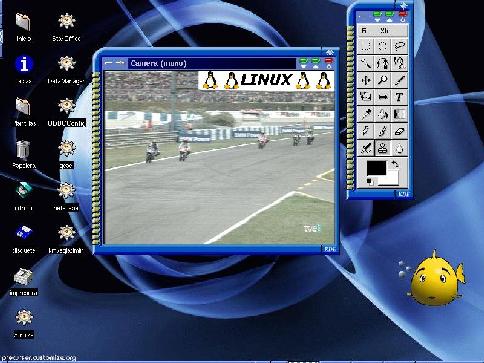
Figure 1. An X window displayed on another PC through PLIP.
In the interest of being practical, I'll describe three testing scenarios, with certain practical effects falling into the category of "things that the human mind can't and shouldn't understand".
Certainly, the PLIP interface isn't the fastest one (I get around 27Kbps); network cards are faster. However:
It is cheap and readily available; there is always a printer port on desktops and laptops, and you only need a simple cable.
Many network concepts are implied; even the lower OSI levels can be seen: level one at the cable, the port and the bit assignment, level two at the Ethernet frame and level three when you do routing.
Many people have been involved in PLIP; using it will be a recognition of their good work.
You can try several PLIP interfaces if you have enough parallel ports and interrupts. In this article, only one will be considered, referred to as plip0.
The cable connections are:
2->15 (D0 -> /ERROR)3->13 (D1 -> SLCT)4->12 (D2 -> PAPOUT)5->10 (D3 -> /ACK)6->11 (D4 -> BUSY)25->25 (GND -> GND)
On the source, plip.c, it is suggested to connect 17->17; this signal is /SLCTOUT, open collector output. Its use is not clear, though, and you can leave it open.
Note its symmetry. It is compatible with the most primitive type of parallel port, unidirectional. Transmission is currently four bits (a nibble) over D0-D3.
The cable has two DB25 male connectors. You can purchase the cable (commonly 1.8 meters in length) or build it yourself. Long cables also work. For long lengths you can connect the Laplink cable and a long 25-pin (DB25) male-female cable.
Cable connection should be done with both PCs off, making sure there is no voltage difference between their parts. If turning off is not feasible, use a piece of wire to connect the metallic parts of both PCs first, or if far away from one another, connect them to a common ground before connecting the cable. You can also take advantage of the metallic covers (shields) surrounding all the pins. If they are interconnected, note that the cover will be the first one to make contact and will nullify any voltage difference. If another signal is the first to make contact, and there is a voltage difference, it may be destroyed.
The general recommendation for cables is to connect the shield to power ground on one end only, but if you have to connect the PCs while they are working, having the connector shields electrically connected can help. This also applies if you build the cable yourself.
Note that if you use a mechanical switch box, the same considerations apply. However, because of the way they are built, the connectors' shields are connected.
PLIP should be a kernel module since you will probably also use the parallel port for a printer (see the Renggli article listed in Resources), and you can't print and use PLIP at the same time. You should understand commands such as depmod -a, lsmod and modprobe modulexx, and files such as /etc/modules.conf and /lib/modules/`uname -r`/modules.dep. You can indicate needed IP addresses in the files /etc/hosts and /etc/networks.
For module support in the kernel, check in .config:
CONFIG_MODULES=y
CONFIG_KMOD=y
If there is more than one network interface, routing will be needed. Sysctl support at General setup as well as /proc file system support at "File Systems" will also be required in the kernel.
In addition, the following should be executed:
echo "1" /proc/sys/net/ipv4/ip_forward
This is probably best done when networking is initialized if you enable routing in your system.
PLIP should work out of the box, but nothing works right the first time. Note that PLIP configuration uses two fundamental utilities: ifconfig to configure the interface and route to define routes.
The fundamental software tools for debugging PLIP are:
ifconfig: you can call ifconfig plip0 at any time. Its output should be similar to that shown in Listing 1.
ping: ping the other end of a PLIP connection and observe (with tcpdump) if you get both a request and a response. I observed that activity stopped in a PC when pinging while in energy conservation with APM; pressing a key started activity again. If this happens, try to wake up your system on the BIOS with the PLIP interrupt.
plipconfig: permits adjustments on PLIP protocol parameters, but speed improvements are small. Try something like this:
plipconfig plip0 nibble 200 trigger 50

Figure 2. A Debugging Device
You can build a device like the one shown in Figure 2, and place it between the parallel port and the cable. The necessary components are:
A male and a female DB25 connector (cable soldering type), soldered back to back.
Nine resistors of at least 1K5 (1500) ohms.
Nine LEDs. Use the red ones, they are the most common and efficient. The longer pin is the anode.
Since PLIP uses D0-D4, it is enough to have resistors and LEDs on D0-D4 only, but for universal use of the device it is better have all data bits connected. Debug the device itself with a DOS floppy and DOS DEBUG ("O" command: output to port, such as "O 378 FF"). If you don't get a response to ping, but see LED activity, you are near success. Don't leave the device connected forever: the few miliamps to light the LEDs are heavy on current consumption.
You can use two of these devices, one at each end of the cable; if doing so, don't include the LED on /ACK, since it will double the load on D3.
One problem with the PLIP protocol is that, being point to point, both ends must work to have any activity. If one or both ends fail, diagnosis may be difficult, and you may not even see anything at all on the LEDs. But on plip.c you will see that for protocol to start, it has to read zeros on the status bits of the printer port. Therefore, you can substitute one of the PCs with one booting from a DOS floppy, execute DOS DEBUG and write zeros on bits D0-D4 of the parallel port (such as "O 378 0"). On the Linux PC, ping the one with DOS (of course, it will not respond). It will think that the other end of the PLIP connection is alive, and it will try to get its attention, interrupting it through /ACK, so you should see pulses on the debugging device on D3 of the Linux PC, or at /ACK on the DOS PC.
Linux PLIP implementation uses a PC interrupt. An interrupt is a real physical signal communicating that a device requires attention from the processor. Intel x86 processors have two interrupt input signals: INTR (maskable) and NMI (not maskable, but can be masked on PCs through external hardware). An external chip, an 8259 PIC programmable interrupt controller, receives up to eight interrupt signals (IRQ0 to IRQ7), and signals the processor through INTR sending a vector indicating the interrupt source. For more than eight interrupts, other 8259s can be cascaded.
IBM designed a poor interrupt system on the first PC in 1981, with a low number of user assignable interrupts (one 8259), which could not be hardware-shared (use the same interrupt for two or more devices at a time) at the ISA-bus level.
In 1983 the AT appeared with some more interrupts: IRQ8 to IRQ15 (cascading two 8259s through IRQ2). But they still could not be shared, so it was of no use for operating systems to be aware of interrupt sharing. You could share interrupts assuming that you would not use the devices simultaneously; doing so could lock the PC. All this has been passed on to the present time, and often you may find yourself short of free interrupt signals.
Fortunately, the PCI bus was designed to permit interrupt sharing. PCI cards normally use the #INTA signal, which gets routed to some IRQx; several #INTA signals can use the same IRQx. The Linux kernel and other operating systems are aware of the possibility of interrupt sharing.
According to the IBM XT Technical Reference Manual, Figure 3 represents an interrupt IRQx on the ISA bus (active high), and two devices that will share it. Device 1 signals an interrupt making INT1 go high. In order to reach the processor, /EINT1 must be low and /EINT2 must be high, so that INT2_O is open. But if /EINT2 were low when device 2 is not active, INT2_O would be low and would short circuit INT1_O to GND.
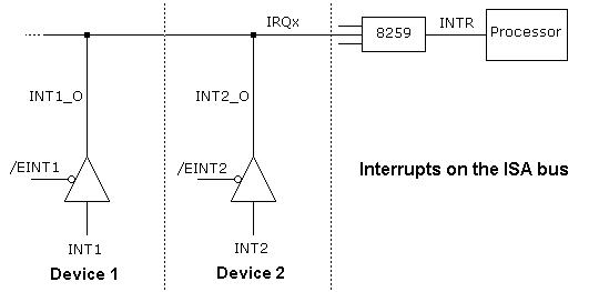
Figure 3. The PC Interrupt System
In practice, interrupt assignment is as follows:
Fixed: IRQ0 (clock), IRQ1 (keyboard), IRQ2 (cascade), IRQ6 (floppy), IRQ8 (rtc) and IRQ13 (coprocessor).
Primary IDE uses IRQ14. Secondary IDE uses IRQ15. PS/2 mouse uses IRQ12. Motherboard's communication ports generally use IRQ3 and IRQ4. Motherboard's printer port and software using interrupt (as PLIP) use IRQ7 or IRQ5.
Remaining assignable interrupts are generally IRQ5 or IRQ7, IRQ9, IRQ10 and IRQ11. If these are not enough, PCI devices should be used since they permit hardware interrupt sharing.
The classical PC parallel printer ports recognized at BIOS time are named and have base addresses as follows:
LPT1: 0x3bc (commonly found on monochrome adapters).
LPT2: 0x378.
LPT3: 0x278.
IBM assigned IRQ7 to LPT1 and LPT2, and IRQ5 for LPT3, but because of interrupt shortage, printing software rarely used interrupt or permitted defining its use.
Since the printer is an output device, these ports were designed as unidirectional. Soon a spare bit was found at the original hardware design (base+2, D6 at high level) that could be connected to disable an output buffer for permitting input; this was advantageous for parallel port cameras and scanners.
Other improvements came as EPP and ECP parallel ports (more on this later) or parallel ports on PCI cards (see www.lpt.com).
Typing cat /proc/parport/*/* shows the parallel ports characteristics:
base:    0x3bc
irq:    none
dma:    none
modes:  SPP
none
+plip0
base:   0x378
irq:    7
dma:    none
modes:  SPP,EPP,ECP,ECPEPP,ECPPS2
7
base:   0x278
irq:    none
dma:    none
modes:  SPP
none
The /etc/conf.modules file describes these characteristics: options parport_pc io=0x3bc,0x378,0x278 irq=none,7,none 0x3bc is on a monochrome adapter card, 0x378 is on the motherboard and 0x278 is on an ISA card.
At home (Figure 4): a desktop (capricho) and a laptop (chinito). Main objective will be sharing an Internet connection at the desktop.
At work (Figure 5): the laptop will be linked to a LAN through capricho. It should access, and be accessed by, the rest of computers in the LAN.
At work (Figure 6): the PLIP linked PCs will emulate a router.

Figure 4. Scenario 1: a Laptop and a Desktop Linked through PLIP.

Figure 5. Scenario 2: a Laptop and a LAN Linked through PLIP.
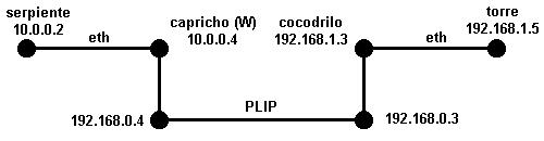
Figure 6. Scenario 3: Two Subnets Linked through PLIP.
Note that capricho at home and at work are different PCs, but having the same name and IP simplifies laptop configuration. When needed, they will be referred to as capricho (H) or capricho (W).
This scenario is simple; see Figure 4. This is the scenario described in Rengglii's article, and an obvious application is sharing an internet connection on a desktop and a laptop. You should keep in mind:
The desktop, having the internet connection, should be the default gateway for the laptop, so the following must be executed at the laptop: route add default gw capricho.
The desktop must do IP masquerading for the laptop. In my kernel 2.2.13, the configuration appears as:
CONFIG_IP_MASQUERADE=y
CONFIG_IP_MASQUERADE_ICMP=y
CONFIG_IP_MASQUERADE_MOD=y
CONFIG_IP_MASQUERADE_IPAUTOFW=m
CONFIG_IP_MASQUERADE_IPPORTFW=m
CONFIG_IP_MASQUERADE_MFW=m
This corresponds to modules ip_masq_autofw.o, ip_masq_portfw.o, ip_masq_mfw.o, ip_masq_user.o, ip_masq_ftp.o, ip_masq_irc.o, ip_masq_raudio.o, ip_masq_quake.o, ip_masq_vdolive.o and ip_masq_cuseeme.o.
A PLIP connection should be faster than common internet connections, so it won't be a bottleneck.
See Figure 5. Compared to scenario 1, I tried using Proxy ARP at capricho so that it would take care of all datagrams sent to chinito. It does so by publishing an ARP entry for chinito that points to its own Ethernet interface, and the command 'arp -s capricho 'ifconfig|grep plip0|awk '{print $5}' 'pub' 'awk' gets the MAC address of chinito PLIP out of ifconfig. Executing this on capricho, when serpiente pings chinito (having no route to it), tcpdump -tni eth0 on capricho shows how serpiente asks about chinito, and capricho answers with its own MAC (0:60:8:72:67:15 and 0:20:af:69:5:60 are the respective MAC addresses of capricho and serpiente):
arp who-has 10.0.0.7 tell 10.0.0.2
arp reply 10.0.0.7 (0:60:8:72:67:15) is-at 0:60:8:72:67:15 (0:20:af:69:5:60)
10.0.0.2 > 10.0.0.7: icmp: echo request
10.0.0.7 > 10.0.0.2: icmp: echo reply
capricho has no free interrupt for PLIP, so I share ISA interrupt IRQ5 between the sound card and an LPT port, and configure PLIP and sound as modules.
As said, when sharing an ISA interrupt, the devices cannot be used at the same time, so using Linux modules works conveniently. Most of what is said in this section won't apply if you don't share ISA interrupts, and your life will be easier.
Interrupting devices must behave well both at the hardware and software level (see Figure 3). Things worked satisfactorily with ISA IRQ5 being shared by a printer port on the motherboard, and an ISA SoundBlaster AWE card, but not with older SoundBlaster 16 Standard or Value. I only tested non-PnP (Plug and Pray) cards. Your mileage may vary widely.
The advantage of sharing an interrupt with the sound card is that you have to reproduce only a sound file to make sure things work when the sound modules are loaded. If you hear only the first tenth of a second of the sound file, surely there is an interrupt problem. You can check interrupts with cat /proc/interrupts and cat /proc/stat.
To use PLIP and sound as modules, they have to know the resources they should use. The relevant lines at /etc/modules.conf are, in my case:
alias parport_lowlevel parport_pc
options parport_pc io=0x3bc,0x378,0x278 irq=none,none,5
alias char-major-14 sb
alias midi awe_wave
options sb io=0x220 irq=5 dma=0 dma16=5 mpu_io=0x330
options adlib_card io=0x388
post-install sb /sbin/modprobe '-k'
'adlib_card'
Parallel port 0x3bc is on a monochrome adapter, 0x378 is on an ISA card and 0x278 is on the motherboard.
I previously tried sharing IRQ7 but, when switching to sound, the keyboard and mouse locked just after executing rmmod plip, if more than one printer port was defined in /etc/modules.conf. I don't see any difference between choosing to share IRQ5 or IRQ7. Again, your mileage may vary.
Since I have no oscilloscope available, I observe interrupts directly at the ISA bus with a resistor and LED attached to a half-a-meter cable and connecting it to jumper pins having interrupt signals, present at old ISA cards. Even with very brief signals, light can be seen on the LED (interrupts go high when activated). Note, however, that if you use the motherboard's parallel port its interrupt may not appear at the ISA bus. If you want to try this debugging trick, use the ISA interrupts shown in Figure 7.
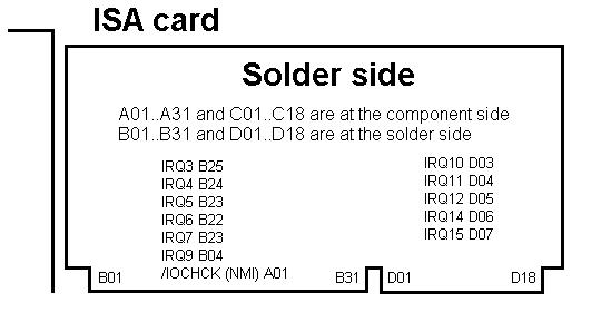
Figure 7. Interrupts Location at the ISA Bus
For switching to sound, the commands are shown in Listing 2 (observe sound test). For switching to PLIP, the commands are shown in Listing 3; as you see, it considers printing. With these scripts I can switch to sound and back to PLIP any number of times. Note that capricho_plip is defined in /etc/networks as having IP address 192.168.0.4 and cocodrilo_plip as 192.168.0.3, as seen in Figure 6.
Listing 2. PLIP Removal and Sound Insertion
Listing 3. Sound Removal and PLIP Insertion
If you use printing, remember that if you use the same port for PLIP and printing, you can adapt the shell scripts found in the Renggli article. A mechanical switch on the printer port, switching into it the printer cable or the PLIP cable, should be used. Note that you can be using sound and printing, or using PLIP, with interrupt assigned to sound or PLIP, but you can also print without interrupts and use sound all the time. Also, if the printing port is not the PLIP one, then, if you have no interrupts available, you can also print without interrupts. Check your /lib/modules/uname -r/modules.dep file for modules to load or unload. You can be using sound or using PLIP, sharing an interrupt and printing all the time on other port. For example, for printing on the second printer port we can use insmod lp parport=1. All this is explained by Philip Bludel (see Resources).
Note that in addition to using the parallel port for printing and PLIP, you can connect different devices, such as a Zip drive, a parallel port IDE adapter, a parallel port camera or a parallel port scanner. So modules removal and insertion modules should be done as follows:
Remove all services provided by other modules.
Remove all other modules.
Insert the module you want.
Enable that module's services.
Another oddity was on the motherboard's parallel port mode, chosen on BIOS. If EPP or ECP, I could not switch back to PLIP after switching to sound. Choosing Normal mode made it work well again. One of those "things that the human mind can't and shouldn't understand".
It has been suggested elsewhere to modify ISA interrupt hardware for true interrupt share inserting diodes; if trying this, you must be sure of what you are doing. If you are faced with lack of interrupts, try to modify your hardware using PCI cards, since that makes true interrupt sharing possible at the hardware level (the same for EISA and MCA buses).
As you can see, sharing an ISA interrupt has so many potential pitfalls, so it may be better not to try it. However, removal and insertion modules proved to work well.
When interconnecting LANs, we think of three types of devices:
Repeaters: frames at one side are blindly repeated at the other; interconnection is near to the OSI physical layer (level 1). Repeaters have no intelligence. Making a PLIP interface work as a repeater would be very inefficient since it is very slow.
Bridges: a bridge learns the MAC addresses of devices at each of its sides, and only sends frames from one side to the other if the destination MAC address is there; it works at the OSI Data Link layer (level 2). Bridging is experimental on 2.2 kernels.
Routers: routers work at the OSI Network layer (level 3) and are more general. Here we will consider a simple implementation. The IP address will be the base to distinguish systems, and hence do the routing functions.
Figure 6 shows routing through two PLIP interconnected PCs. Note that PLIP IP's (192.168.0.X) are somehow virtual: it should work choosing addresses of one or the other subnet.
Routing has to be enabled at both capricho and cocodrilo, and the PCs on each network have to have the PLIP-connected ones as their default gateway:
serpiente: route add default gateway capricho
torre: 192.168.1.3 (cocodrilo) is assigned graphically within its network configuration. capricho and cocodrilo have to be told that they can reach the other network through the PLIP interface, such as:
capricho: route add -net 192.168.1.0 netmask 255.255.255.0 dev plip0
cocodrilo: route add -net 10.0.0.0 netmask 255.0.0.0 dev plip0
Bob Edwards and Bill Ball (see Resources) can give you many other ideas.
It has been mentioned that PCI provides a good solution for one of the weak points in the PC architecture: true interrupt sharing. According to Rubini (see Resources), the following prototype should be obeyed for sharing interrupts: int request_irq(unsigned int irq, void (*handler)(int, void*, struct pt_regs*), unsigned long flags, const char *device, void *dev_id); Bits in flags must be SA_SHIRQ.
To test PLIP on a PCI parallel port, I installed a PCI card with two serial ports and one parallel port on capricho (W). Unfortunately, plip.c was not written considering interrupt sharing, so to test PLIP I had to extract the PCI LAN card (see configuration below).
Typing lspci -v (or cat /proc/pci in older kernels) shows the ports used by the PCI card:
00:09.0 Parallel controller:
Lava Computer mfg Inc: Unknown device 8800
(prog-if 01 [BiDir])
Flags: slow devsel, IRQ 11
I/O ports at d400
00:09.1 Serial controller:
Lava Computer mfg Inc: Unknown device 0900
(prog-if 02 [16550])
Flags: slow devsel, IRQ 11
I/O ports at d000
I/O ports at b800
Parallel ports definition at /etc/modules.conf is: options parport_pc io=0x3bc,0x378,0x278,0xd400 irq=none,none,5,11.
On the SuSE distribution, PLIP interfaces are defined by yast, but the following should work:
ifconfig plip1 10.0.0.8 irq 11 io_addr 0xd400 pointopoint 10.0.0.7 up
PLIP worked without problems, despite acting as a second PLIP interface, connected to the laptop.
Kernel serial.c was not written with full interrupt sharing in mind, but the one in serial.sourceforge.net worked perfectly. For defining the serial ports I executed:
setserial -v /dev/ttyS14 port 0xd000 irq 11 autoconfigsetserial -v /dev/ttyS15 port 0xb800 irq 11 autoconfig
See cat /proc/interrupts on Listing 4; observe sharing in IRQ11. It was obtained with a continuous ping on the LAN card, two external modems attached to the PCI serial ports (running minicom on them), and PLIP on motherboard's parallel port (parport2), also with a continuous ping.
Listing 4. Capture from cat/proc/interrupts on capricho (W)
A similar experiment worked with capricho (H) with IRQ11 being shared by a network card, the motherboard's USB controller, bttv.o (video4linux) and the PCI serial ports (see Listing 5). Incidentally, on /etc/modules.conf I had to define the PCI parallel port without using interrupt:
options parport_pc io=0x3bc,0x378,0xb800 irq=none,7,none
Substituting that last "none" above with "11", thereby forcing PLIP parallel port on 0xb800 to share its interrupt (as informed by lspci -v) caused the PC to lock when booting. So if you use PLIP on a PCI parallel port and try sharing its interrupt, be wary.
chinito: an AMD 450 laptop with Esware 1.1 (a Spanish Red Hat-type distribution). Kernel is 2.2.12-20.
capricho (H): Pentium II-350 desktop with SuSE 6.3. Kernel is 2.2.13. It is overclocked, with 112MHz FSB frequency.
capricho (W): Pentium MMX-200 desktop with the same SuSE 6.3. It is overclocked, with motherboard's frequency set at 75 or 83MHz through the turbo switch (an overclocker's trick). Its interrupt usage is: ttyS1/IRQ3 (external modem), ttyS2/IRQ4 (infrared dongle), motherboard's printer port (PLIP) and a SoundBlaster AWE share (one or the other) IRQ5, ttyS3/IRQ7 (ISA card), ttyS0/IRQ9 (ISA card), IDE4/IRQ10 (on sound card), graphic card, LAN card and USB controller share (truly) IRQ11, PS/2 mouse uses IRQ12, IDE1/IRQ14, and IDE2/IRQ15. IRQs 0, 1, 2, 6, 8 and 13 are assigned by the hardware. The added PCI card with two serial ports and one parallel port also shares IRQ11.
cocodrilo: Pentium 133 desktop with same Esware as above.
serpiente: Pentium 166 with an old 2.0 kernel.
torre: Pentium 100 with a popular graphic operating system. PLIP works on overclocked PCs.
Configuring Linux linuxconf for Red Hat or Esware, and yast for SuSE, will make your life easier. Details of ifconfig, route and enabling routing will be hidden.
Many thanks to the PLIP originators and developers, to people with any kind of relation to it, and to Juan Carlos Escobar, who, in his spare time, has shared his infinite networking knowledge.
Javier Vizcaino (center) lives in Madrid. He is an Industrial Engineer and has a Master's Degree in Electrical Engineering from Stanford University. He may be found in one of two stable states: digging inside an open PC or practicing radio-controlled gas car racing. E-mails related to this article can be addressed to javizca@bbvnet.com.
email: javizca@bbvnet.com
