Linux-Powered Amateur Rocket Goes USB
In summer 2005, I stood on a sandy hill a couple miles east of Bend, Oregon. Through my binoculars, I could see people scattered in a distant ring around our 12-foot amateur rocket, waiting to take pictures when it launched. A mile away, I could see the tents and cars at ground control.
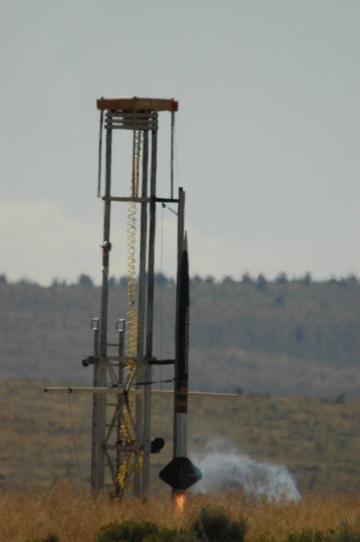
Figure 1. Portland State Aerospace Society Rocket Launch (Photo Credit: Dave Sharp)
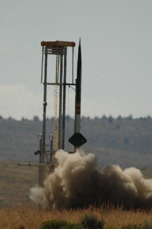
Figure 2. Rocket Launch, Part II (Photo Credit: Dave Sharp)
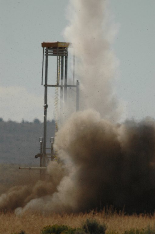
Figure 3. Rocket Launch, Part III (Photo Credit: Dave Sharp)
I was part of a recovery team for the Portland State Aerospace Society (PSAS). PSAS is a completely open-source aerospace engineering group. You can take our open-source software and open hardware designs from our Web site (see Resources) and make your own rocket. Our long-term goal is to guide our rocket into space actively and put a cube satellite into orbit.
That summer day, we weren't going into orbit; we were just testing our latest rocket. Our rocket would launch, deploy its parachute at about 18,000 feet above the ground, and then drift safely to the ground, all the while spewing sensor data over our 802.11 wireless telemetry link. Once the rocket had landed, the recovery teams would use the GPS coordinates to find the rocket.
Over my 2-meter ham radio, I could hear Andrew Greenberg (PSAS's self-proclaimed “benevolent dictator”) warning the bystanders at the launch site that the rocket motor was about to go live. The DTMF tones to arm the rocket followed.
“...3...2...1. We have liftoff!” The ground crew could see the streaming video from the rocket showing the ground become farther and farther away. The Java RocketView software displayed the rocket's sensor data: GPS coordinates, acceleration, rotation, pressure and the state of all the rocket's subsystems. Everything looked good.
I watched the rocket get smaller and smaller as it shot into the sky. The Linux flight computer on board the rocket would evaluate all the sensor data and decide when to deploy the parachute. The parachute needed to be deployed in the five-second window when the rocket reached its peak altitude (apogee), slowed down and started to fall downward.

Figure 4. RocketView Screenshot (Photo Credit: Jamey Sharp)
At ground control, the crew watched the flight computer decide to deploy the drogue shoot. Everyone cheered, because the hard part of the flight was over. Or so we thought.
Five seconds later, the flight computer figured out that the rocket was still falling. It tried to deploy the main parachute, but it was still accelerating, as if the parachutes hadn't deployed. Something was wrong. Andrew frantically began to send the DTMF tones to the rocket for an emergency parachute deployment. The flight computer reported seeing the DTMF tones, but the rocket continued to plummet toward the ground.
Thirteen seconds later, the link to the flight computer was dead. The last known speed was more than 500mph, with a GPS reading about 1,000 feet off the ground. The depressed ground crew relayed the last-known latitude and longitude from RocketView.
Dave Allen, my fellow recovery team member, was eager to get to the rocket first. Dave and I got as close to the GPS coordinates as we could using the road and a four-wheel drive. Then we started hiking through the desert.
Finally, I spotted a glint of metal in the middle of a scrub brush. About a foot of rocket was sticking out of the ground. If we didn't have the GPS coordinates, it would have been impossible to find.
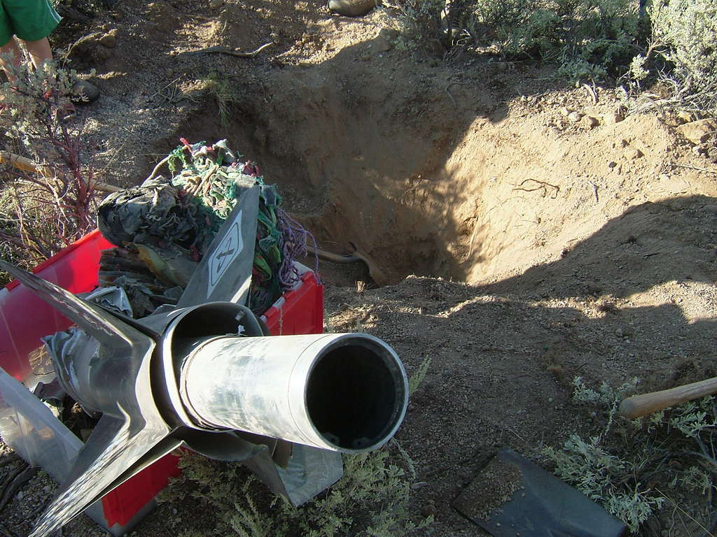
Figure 5. Rocket Crash (Photo Credit: Sarah Sharp)
PSAS members showed up and we began to dig the rocket out. Our 12-foot rocket had been compressed into a three-foot piece of twisted metal. The electronics were dust and bits of broken silicon. Amazingly, Baker, our sock monkey survived. He was a little squished, and his helmet was ripped, but he would fly another day.
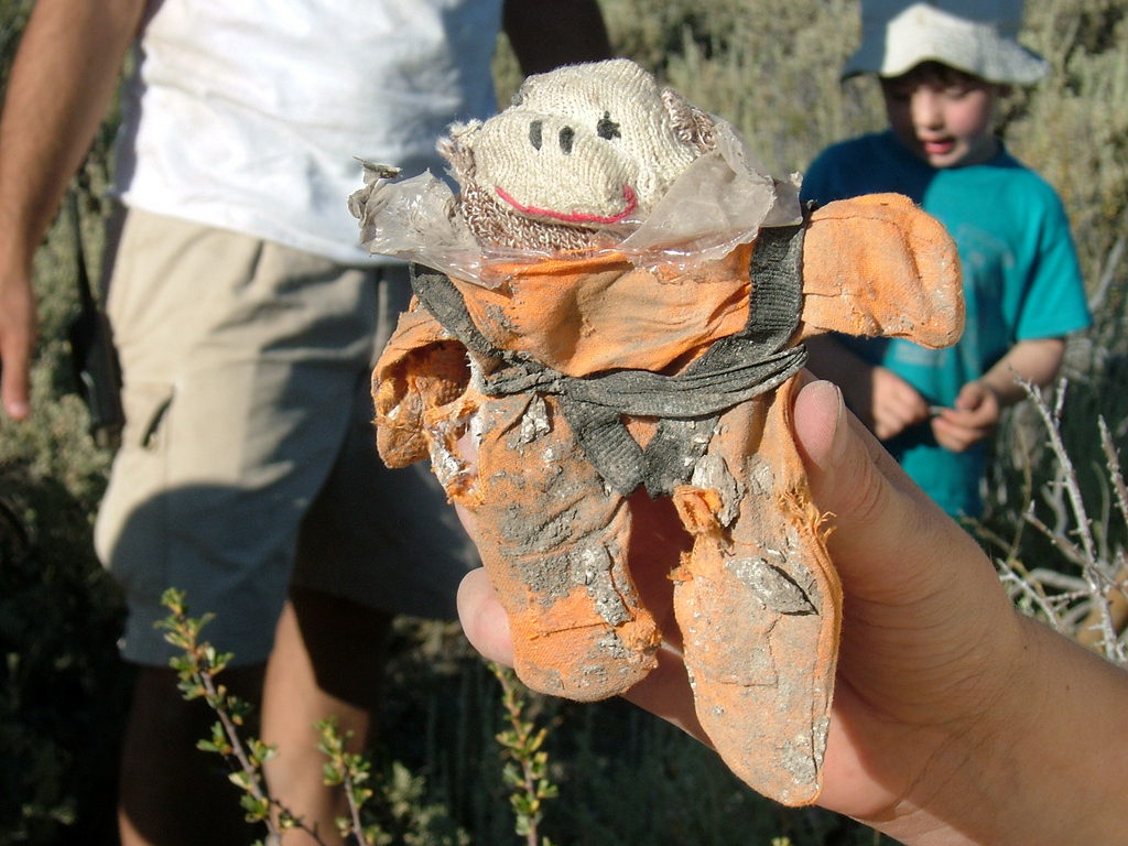
Figure 6. Maggie Emery Holding Baker the Sock Monkey, with Solomon Greenberg in the Background (Photo Credit: Sarah Sharp)
After the 2005 crash, it would have been easy for PSAS to rebuild the rocket using this data. We toyed with the idea of rebuilding it exactly like the old rocket, but then “second system syndrome” set in. We just had to make the new rocket better than the old rocket.
The airframe team decided to redesign the airframe and the pyrotechnic parachute deployment system, as PSAS had concluded that was the point of failure for our launch. The avionics team decided to upgrade our flight computer from a 100MHz AMD Elan to a 400MHz Freescale MPC5200 (purchased with a grant from IBM).
The avionics team also wanted to upgrade the various avionics subsystems. We wanted the GPS, inertial measurement unit and all the other avionics sensor “nodes” to get data to the flight computer faster. The old rocket used 8-bit PIC microcontrollers that communicated over the Controller Area Network (CAN) bus. The avionics team wanted faster microcontrollers and a faster bus that was easier to develop software for.
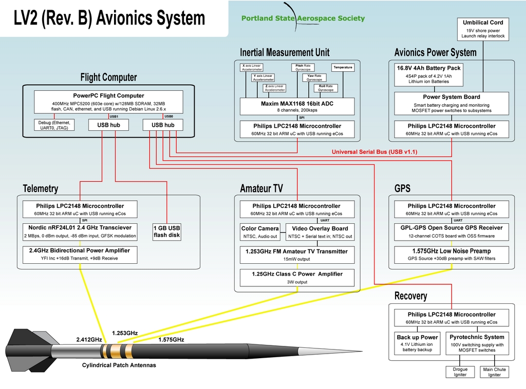
Figure 7. New PSAS Avionics (Credit: Andrew Greenberg)
I was part of the Portland State University senior capstone project that was assigned the task of upgrading the avionics bus and sensor node microcontrollers. After much debate and argument within PSAS, we decided to replace the 1Mb CAN bus with a 12Mb full-speed USB. We chose a 32-bit ARM microcontroller, NXP's LPC2148 (see Resources).
The LPC2148 made the cut above the other 64-pin ARMs with USB because it already had an open-source library (LPCUSB) that would bootstrap the chip and control the USB peripheral. The main LPCUSB developer, Bertrik, was kind enough to let some PSAS members have commit access to the SVN repository, and PSAS has been contributing new features since then.
Choosing the LPC2148 also allowed us to pick from some very inexpensive hardware. An Olimex LPC2148 development board with USB, serial, JTAG and a built-in breakout area can be purchased for about $75. The Olimex JTAG programmers are about $50, and the free and open-source OpenOCD Project can be used to program the LPC2148 over the JTAG port. This makes it easy and cheap to build your own rocket avionics node at home.
You also can program LPC2148 to be whatever kind of USB device you want. The LPC2148 supports all four types of USB transfers and has enough Flash (32KB) and RAM (512KB) to support a moderate amount of code. Hardware hackers also will like the fact that it has I2C, SPI and plenty of GPIO pins. The LPCUSB library already supports several different USB applications, such as a USB COM (serial) device and a mass storage device (Flash drive). These examples easily can be hacked to create custom USB devices.
If you want to start playing around with the LPC2148, you need to set up a development environment with a few different tools: an ARM-ELF cross compiler (for compiling code on a Linux box to ARM machine code), install tools for downloading the binary to the LPC2148, install host-side software to talk to the board and (optionally) the Eclipse IDE to set breakpoints on the LPC2148 and step through the code.
Fortunately, Dave Camarillo and Kay Wilson made a set of scripts to install and download all the necessary software and bundled them into a git repository with the PSAS LPC2148 source code:
$ git clone git://git.psas.pdx.edu/git/lpc-kit.git
The examples in this article assume you cloned the git repository from your $HOME/git/ directory.
Read the installation directions in the Doc/ directory. The psas_lpc_setup.pdf describes the hardware setup and what the scripts are trying to install. The scripts assume you're running on a Debian or Ubuntu Linux box, but they easily can be modified to run on an RPM-based distro.
Once you've run the shell scripts in the Tools/ directory, you can compile and download the simple serial example in the Dev/2148/poke/src/ directory to the LPC2148. The whole process is documented in the “Example Programming” section of psas_lpc_setup.pdf. The document walks you through setting up the cables, making the sample code by using the Makefile in Dev/2148/poke/src/ and using OpenOCD to program the LPC2148 board.

Figure 8. LPC2148 Example Setup (Photo Credit: Sarah Sharp)
When you plug the reprogrammed LPC2148 in to an RS-232 port into your computer, a TTY device is created. If you're using a straight-through serial cable, /dev/ttyS0 is used. If you're using a USB-to-serial adapter, /dev/ttyUSB0 is created. Then, you can use minicom, or any other terminal emulator, to talk to the LPC2148 board. The default minicom settings (115200 baud rate, 8N1) are fine.
The reprogrammed LPC2148 echoes back whatever you type and outputs messages when you press the round black buttons on the board. This simple example should allow you to verify your build environment and ensure that you can talk to your board over the serial port.
The more interesting project is to get the LPC2148 to communicate over USB. The LPC2148 supports four different USB transfer types: control, bulk, interrupt and isochronous. A USB device can have several data pipes, or “endpoints”, that implement one of the transfer types. Each endpoint can either send data to the host (an IN endpoint) or send data from the host (an OUT endpoint). Control endpoints are bidirectional.
All USB devices must have one control endpoint over which to send their device descriptors. PSAS needed one other IN endpoint to send over periodically sampled sensor data, so we wanted either an interrupt or an isochronous IN endpoint. We always want to receive the latest data, so we chose the isochronous IN endpoint, because the host controller software will never attempt to retry a dropped isochronous transfer. Isochronous endpoints also could be used to turn the LPC2148 into a USB camera.
Dave and Kay recently added isochronous transfer and DMA support to the LPCUSB library. To try it out, you need to check out the latest code from the LPCUSB SVN repository:
$ svn co https://lpcusb.svn.sourceforge.net/svnroot/lpcusb lpcusb
I checked out version 177 into my $HOME/svn/ directory. Throughout these examples, I assume you use the same directories.
There should be an isochronous example in lpcusb/trunk/target/examples/ called isoc_io_dma_sample.c. This is a simple program for the LPC2148 that creates two isochronous endpoints. The IN isochronous endpoint sends a counter value into the host and then increments the counter. The OUT endpoint allows the host to control whether LED1 on the board is on or off.
To build the isoc example, change directories to lpcusb/trunk/target and type make. You now should have a file called isoc_io_dma_sample.hex in the examples directory.
Now you need to flash the .hex file to the LPC2148 board. You need to use the OpenOCD config file from the lpc-kit, and modify the OpenOCD script to download the correct .hex file.
First, copy the OpenOCD template script from lpc-kit:
$ cd ~/svn/lpcusb/trunk/target/examples/
$ cp ~/git/lpc-kit/Dev/2148/lpc-template/src/
↪oocd_flash_lpc2148.script .
Also, copy the OpenOCD config file into the LPCUSB examples directory:
$ cp ~/git/lpc-kit/Config/2148/openocd_lpc2148_v1257.cfg .
Now, modify the script to tell OpenOCD to send the isoc_io_dma_sample.hex file to the LPC2148. Change this line:
flash write_image template.hex 0x0 ihex
to:
flash write_image isoc_io_dma_sample.hex 0x0 ihex
Next, start the OpenOCD dæmon:
$ sudo ~/git/lpc-kit/LPC/2148/OCD/bin/openocd \
       -f openocd_lpc2148_v1257.cfg
From another terminal, Telnet into the OpenOCD port, and then tell OpenOCD to run the modified script:
$ cd ~/svn/lpcusb/trunk/target/examples/
$ telnet localhost 4444
Trying 127.0.0.1...
Connected to localhost.
Escape character is '^]'.
Open On-Chip Debugger
> script oocd_flash_lpc2148.script
If you've followed the instructions, LED2 on the Olimex board will start to blink incessantly, and you should see an OpenOCD message similar to the following:
wrote 9454 byte from file isoc_io_dma_sample.hex
                in 0.994377s (9.284629 kb/s)
Close the connection by pressing Ctrl-] and then Ctrl-D. Kill the OpenOCD dæmon in the other terminal by typing Ctrl-C. Remove the JTAG connector, press the LPC2148 reset button, and connect a USB cable from the Olimex board to your computer's USB port. Make sure to plug in to a root port, not through a USB hub. Some hubs have issues with isochronous transfers, so a direct connection is best. You can power the LPC2148 solely off USB bus power, but I left the 9V wall wart plugged in.
If you have CONFIG_USB_DEBUG turned on in your Linux kernel config, you will be able to watch the USB subsystem connect to the USB device as you plug it in:
$ sudo tail -f /var/log/kern.log
... usb 2-2: New USB device found, idVendor=ffff, idProduct=0005
... usb 2-2: New USB device strings: Mfr=1, Product=2, SerialNumber=3
... usb 2-2: Product: USBSerial
... usb 2-2: Manufacturer: LPCUSB
... usb 2-2: SerialNumber: DEADC0DE
Type sudo lsusb to see which USB devices are connected to your system. You should see a device with an ID of ffff:0005. For me, it showed up as device 15:
$ sudo lsusb
Bus 003 Device 001: ID 1d6b:0002 Linux Foundation 2.0 root hub
Bus 002 Device 015: ID ffff:0005
Bus 002 Device 001: ID 1d6b:0001 Linux Foundation 1.1 root hub
Bus 001 Device 001: ID 1d6b:0001 Linux Foundation 1.1 root hub
You can use the -v flag to examine the full device descriptors. This outputs all descriptors for all devices, so it's best to limit the output to the LPC2148 device with the -d <ID> option:
$ sudo lsusb -v -d ffff:0005
You should see two endpoint descriptors, one for an isochronous OUT endpoint and one for an isochronous IN endpoint.
Congratulations! The Linux kernel can initialize the LPC2148 USB device successfully. Unfortunately, there is no standard Linux USB kernel driver for this device. Instead, you need to compile and run a user-space program that uses the Linux kernel USB interface (usbfs) to talk to the device directly.
First, you need to have the libusb-dev package installed to get the usb.h header file for usbfs:
$ sudo aptitude install libusb-dev
Now, change directories into the lpcusb host-side code examples:
$ cd ~/svn/lpcusb/trunk/host/linux_isoc_sample/
Type make. This creates src/linux_usbfs_isoc_io_test, a binary that needs to run as root. Type sudo src/linux_usbfs_isoc_io_test to talk to the USB device. You will see lots of messages scroll by, similar to the following:
Bytes/second 1226
Input Length 4 number sent from device 0x3116D4 ret 0 status 0 flag 2
error_count 0 number_of_packets 1 actual_length 0 start_frame 614
usercontext -1077961592 iso_frame_desc[0].actual_length 0
iso_frame_desc[0].length 128 iso_frame_desc[0].status 0

Bytes/second 1228
Input Length 4 number sent from device 0x3116D5 ret 0 status 0 flag 2
error_count 0 number_of_packets 1 actual_length 0 start_frame 615
usercontext -1077961592 iso_frame_desc[0].actual_length 0
iso_frame_desc[0].length 128 iso_frame_desc[0].status 0
The start_frame is the USB bus “frame number” in which the transfer started. A frame represents a one millisecond time period. As long as you see steadily incrementing start_frame numbers, you know the system isn't dropping isochronous packets. The hexidecimal “number sent from device” is the counter on the LPC2148 that is incremented when the interrupt handler is run and there's an isochronous IN transfer to send to the host.
The isochronous IN endpoint is working correctly if the start_frame and device counter are incremented at the same rate. They may be out of sync for the last couple transfers when you kill the program by pressing Ctrl-C. You also can tell whether the isochronous OUT endpoint is working if the LED1 on the board turns on and off every second.
This very simple code could be extended to make all sorts of USB devices. The isochronous IN endpoint could send sensor data like temperature, pressure or GPS readings. It also could send video, still frames or audio data. It even could be hooked up to a motion detector. The possibilities are endless with the Olimex's breakout board.
If you want to follow the Portland State Aerospace Society's development of LPC2148 USB avionics sensor nodes, join the psas-avionics list (see Resources).
PSAS hopes to do an airframe-only launch in Bend, Oregon, this summer. Our goal is to have working USB avionics nodes and a working Linux flight computer by October 2009. On October 2–4, the Arizona High Power Rocketry Association hosts the BALLS amateur rocketry event. If you're at the BALLS event in the Black Rock Desert of Nevada, or if you're still hanging around after Burning Man, stop by and say hello.
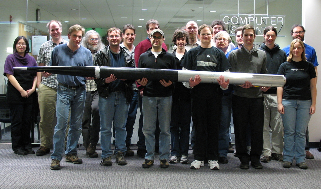
Figure 9. PSAS 2009 Group Photo (Photo Credit: Sarah Sharp). Front row, left to right: Ken Zeigler, Jason Peterson, Andrew Greenberg, Daniel Heinlein, Nathan Bergey, Sarah Sharp. Middle row, left to right: Fletcher Hazlehurst and Frank Mathew. Back row, left to right: Ai Ling Chen, Jeremy Booth, Tim Brandon, Dave Camarillo, Kay Wilson, Mike Engstrom, Jamey Sharp, Josh Triplett, Theo Hill, Ian Osgood. Active PSAS members not pictured: Dan Kirkpatrick and Maria Webster.
Resources
Portland State Aerospace Society: psas.pdx.edu
NXP's LPC2148: www.nxp.com/pip/LPC2141_42_44_46_48_4.html
LPCUSB Wiki: wiki.sikken.nl/index.php?title=LPCUSB
svcs.cs.pdx.edu Mailing Lists: lists.psas.pdx.edu/mailman/listinfo
BALLS 18: www.balls17.com
Sarah Sharp graduated from Portland State University in 2007, but she continues to be an active member of the Portland State Aerospace Society. Sarah currently works at Intel's Open Source Technology Center as a Linux USB kernel hacker. Her blog can be found at sarah.thesharps.us.