
Fun with the iRobot Create
Very little in the Linux universe interacts directly with the physical world. Although you may have peripherals that allow you to work with the computer, the computer has no way to interact with you. This is easily solvable by creating a robot for it to control. iRobot, famous for its Roombas, has created an educational robot called the iRobot Create, based on the Roomba, that is incredibly easy to work with. The Create provides a simple base to extend upon with very little effort. Some people even have mounted an old laptop to the robot to allow mobility, but that is overkill for most situations. It's not hard to create a link between a Linux box and the Create, even though it lacks official support.
The easiest way to interact with the Create is through a serial link using the cable that comes with the robot. For some computers, you may need a USB-to-serial adapter; however, they are readily available for less than $15. The connection will be a TTY serial, such as /dev/ttyS0, or if you are using a USB adapter, the connection most likely will show up as /dev/ttyUSB0.
In order to pass commands back and forth though the serial cable, the easiest tool to use is a serial port terminal. There are several versions of this type of software available. Here, I use gtkterm, a GUI terminal, but if you prefer CLI tools, both screen and minicom will work. After installing and launching gtkterm, you have to set the correct port under Configuration→Port. The port will be the device specified earlier, and if you are unsure which number to choose, you may have to try them all. The speed should be set to 57600 (baud). The other default settings (No parity, 8-bit, 1 stopbit and no flow control) are fine. I also prefer to turn on Local echo, which also is under Configuration and lets you see what you type.
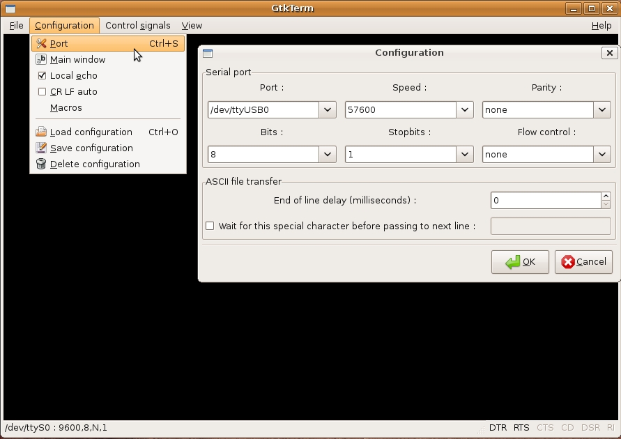
Figure 1. Configuration Options for gtkterm
To test the configuration, plug in the Create to charge and connect it to your computer. The terminal should start displaying lines such as the following every second:
bat: min 0 sec 11 mV 16699 mA 566 deg-C 21
Unless you plan on mounting a computer to the robot itself, the serial cable will prove cumbersome as soon as the robot begins to move. To get around this, the robot needs to go wireless. Although 802.11 Wi-Fi has become ubiquitous on laptops, it is not common on embedded systems like the Create. Another candidate is Bluetooth, which also is becoming widespread; however, Bluetooth modules generally are expensive, have hit-or-miss Linux support and are very short-ranged. Recently, Maxstream's line of XBee radios have been gaining popularity in projects like this. They are very similar to Bluetooth modems and are better suited for this type of project.
All of the parts for this project can be purchased at SparkFun and are listed in Table 1. In addition to these items, you also will need some basic tools and supplies, such as a breadboard, wire and a soldering iron.
Table 1. SparkFun BOM
| Part # | Description | Quantity | Price Each | |
|---|---|---|---|---|
| WRL-08664 | XBee Module | 2 | $24.95 | |
| WRL-08687 | USB XBee Explorer | 1 | $24.95 | |
| BOB-08276 | XBee Breakout Board | 1 | $2.95 | |
| PRT-08272 | XBee Socket | 2 | $1.00 | |
| BOB-08745 | Level Converter | 1 | $1.95 | |
| PRT-00116 | Male Header Pins | 1 | $2.50 | |
| COM-00526 | 3.3V | Regulator | 1 | $1.95 |
| COM-08375 | 0.1 uF Filtering Capacitor | 1 | $0.25 | |
| PRT-08287 | Male DB-25 Connector | 1 | $0.95 |
First, you need to configure your two XBee modules. To start, plug one of them in to the USB XBee explorer and connect it to your computer via USB cable (the USB XBee explorer is simply a serial-to-USB converter board that accepts an XBee module). Using gtkterm again, set it up to listen on a USB port (most likely /dev/ttyUSB0), and set the speed to 9600 baud. Type into the terminal +++, and the module should reply OK.
The module now is ready to be configured. Type in ATID3330,DH0,DL1,MY0,BD6,WR,CN, and after each comma, the module will reply with OK. Remove this XBee, and insert the other one. Again, type +++, and wait for the OK to enter into configuration mode. This time, however, configure it with ATID3330,DH0,DL0,MY1,BD6,WR,CN. Each module is configured to be on network 0x3330 and to send data directly to the other at 57600 baud. One module is connected to the computer, and the other to the Create. The modules are interchangeable—either one can be connected to the computer or the Create.
Next, build the circuit to connect the XBee with the Create serially. This circuit connects the 3.3-volt XBee to the 5-volt Create. To start, solder the two sockets into the XBee breakout board. The easiest way to do this is to place the sockets on the XBee module itself, flip it over, and place the breakout board on top.
After the sockets are soldered, remove the module and solder four wires to VCC, DOUT, DIN and GND. After that, solder four more wires to the male DB-25 connector on pins 1, 2, 8 and 21. The pins should be labeled, although the markings are faint. Next, break off two six-pin lengths from the strip of male header pins, and solder them to each side of the level converter. Again, it is easiest if you use the breadboard as a jig to hold the pins straight as you solder them. Finally, assemble everything according to the schematic (Figure 2) and/or the breadboard wiring diagram (Figure 3). The completed breadboard is shown in Figures 4 and 5.

Figure 2. Schematic for the XBee/Create Interface

Figure 3. Breadboard Wiring Diagram for the XBee/Create Interface
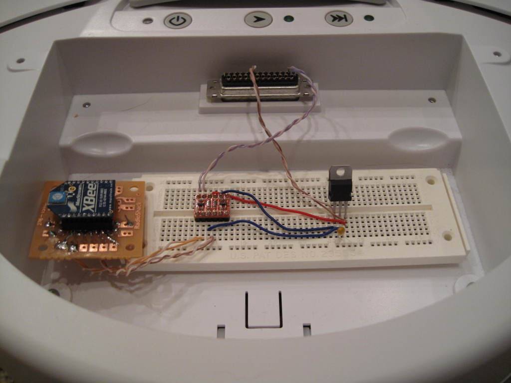
Figure 4. Overview of Electronics Components

Figure 5. Overview of the Create with All Components Installed
Plug the DB-25 connector in to the Create's expansion port, and remove the command module if present. With the other XBee plugged in to your computer, set up gtkterm to communicate with it at 57600 baud. As before, plug the Create in to charge, and with luck, you will see some output on the terminal, and the RX light on the USB explorer should blink. If not, check your connections and configuration.
Even if you did not decide to go wireless, you still can control the Create in exactly the same way. The Create, and most Roombas, implement the iRobot Open Interface protocol, or OI for short. On the computer side, let's use Python to communicate with the Create using iRobot's implementation of OI in Python. This allows you to work on a higher level and not worry about opcodes and such. You will need pySerial and openinterface.py (see Resources). There is a small bug in openinterface.py that can make it difficult to work with on Linux. The simplest way to solve this is to run this sed command in the same directory as the file:
$ sed -ie "803s/ - 1//" openinterface.py
Alternatively, you can remove - 1 manually from line 803.
The library is easy to use—for example, to drive the Create forward at full speed, do this:
import openinterface as oi
PORT = "/dev/ttyUSB0"           # change to your serial port
bot  = oi.CreateBot(com_port=PORT,mode="full")

bot.drive_straight(500)         # drive forward, full speed
In order to access sensor data, you need to request it. If you use bot.stream_sensors(), the Create will update the specified sensors in each argument automatically every 15 milliseconds. To stop, execute bot.stop_streaming_sensors(). Although you can specify manually which sensors you want to stream, it generally is easiest just to stream all of them.
Driving also is pretty simple. bot.drive() takes two arguments: speed and turning radius. Speed is an integer between 500 and –500, specifying the average speed of the wheels in millimeters per second, with negative values corresponding to going backward. Turning radius is a number between 200 and –200, specifying the radius of a turn in millimeters. Positive values turn left, and negative values turn right. There also are special methods that can be used for going straight and turning in place.
The following code uses sensor data to drive and maneuver around obstacles:
bot.stream_sensors(6)                 # packet 6 -- all sensors

while True:                           # loop forever
    if bot.sensors["bump-left?"]:     # is it pressed?
        bot.drive(-500, 10)           # spin to maneuverer
        bot.wait(5)                   # spin for 5 cycles
    elif bot.sensors["bump-right?"]:  # other direction
        bot.drive(500, 10)
        bot.wait(5)
    else:
        bot.drive_straight(500)       # otherwise, go forward
        bot.wait()                    # prevents excess cycling
You can access the Create's song-playing abilities very easily too, and you can store songs in the 17 available song slots. Use bot.define_song() to store a song. The first argument is the song slot where the song will be stored, and you also use this value later to play the song back. The rest of the arguments are notes, represented by tuples of pitch and length. Length is measured in 64ths of a second. Call bot.play_song() to play the song. I'm no musical genius, so hopefully you can write a better tune:
bot.define_song(1,            # index of song
                ("G1", 16),   # note tuples
                ("G2", 16),   # note, duration
                ("G3", 64),   # 64 = 1 second
                ("G9", 16))   # up to 100 notes
# ...snip...
bot.play_song(1)
To control the Create wirelessly with a joystick and Python, we can use pygame (the full details of the pygame joystick API are beyond the scope of the article; check the documentation for more information):
import pygame
from pygame import locals
pygame.init()
js = pygame.joystick.Joystick(0)     # create joystick
js.init()

import openinterface as oi
PORT = "/dev/ttyUSB0"                # change to your serial port
bot  = oi.CreateBot(com_port=PORT,mode="full")

while True:
    if js.getAxis(0) > 0:
        turn = 1 - js.getAxis(0)
    else:
        turn = -(1 + js.getAxis(0))
    bot.drive(js.getAxis(1)*500, turn*200)
    bot.wait()
This code allows you to use a joystick (autodetected) to have primitive control over the Create. The x-axis value has to be manipulated so that when in a neutral position, the robot moves straight and does not spin.
Where to go from here? That's up to you. On the hardware side, you can attach additional hardware to the Create and control it through its digital inputs and outputs (see OI specifications for pin-outs). However, with just the base and some software, there still are tons of possibilities. For example, you could turn the Create into an alarm clock reminiscent of Clocky, the clock that drives around the room forcing you to get out of bed to shut it off. Or, if you are more mathematically inclined, you could use the the “distance” and “angle” sensors to map out a room.
Resources
SparkFun Electronics: www.sparkfun.com
iRobot Open Interface Specification: www.irobot.com/filelibrary/pdfs/hrd/create/Create%20Open%20Interface_v2.pdf
pySerial: pyserial.wiki.sourceforge.net/pySerial
openinterface.py: createforums.irobot.com/irobotcreate/attachments/irobotcreate/Create_Support/792/2/openinterface.py
pygame: www.pygame.org
Zach Banks is an experimenter who is stuck between hardware and software. He's glad to accept comments and questions at zjbanks@gmail.com.
