Controlling a Pinball Machine Using Linux
An old electronic pinball machine is fascinating because it embodies complexity just within the grasp of a jack-of-all-trades hacker. You can learn how one works by visiting the open-source repository known as the US Patent and Trademark Office. The Bally Manufacturing Corporation used a system built around its AS2518 Microprocessor Unit (MPU) described by US Patent 4,198,051 in more than 350,000 units from 1977 to 1985. Maybe you remember playing Evel Knievel, KISS, Mata Hari or Space Invaders?
At the moment, you can buy most nonworking games for less than $250. Many come with original documentation that includes circuit schematics. Combined with what you can learn from the patents and other publications, plus your knowledge of PC hardware and free, open-source software, you can hack together something unique: a working, Web-enabled, classic pinball machine that plays by your rules, running your programs. You can do it legally, for less than the cost of a replacement MPU board, with an old PC and a stock Linux distribution like Fedora.
Reverse engineering the AS2518 MPU was the subject of my Master's thesis in Industrial Technology. Nonworking games often suffer the same tragic design flaw we see on old computer motherboards. Figure 1 shows the damage caused by a leaking Ni-Cad battery that was soldered directly onto the MPU. It ruins not only the electrical connections in IC sockets, but also corrodes the wiring harnesses joining the MPU to the rest of the system.
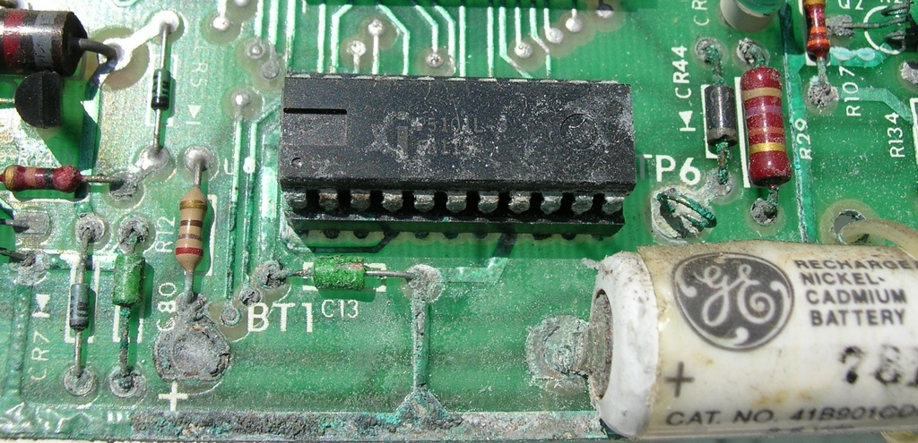
Figure 1. Corrosion on an AS2518 MPU Board
The other circuit boards are usually still intact. When you start working on your game, check the voltages at the test points to make sure. I chose to neuter the flaky +5 VDC circuit altogether and use the power supply from the PC. With the MPU removed, you are left with four wire harnesses holding a total of 66 wires. To connect your PC to the pinball machine, you will want to build an interface board with matching header pins. The design goal is to produce the same inputs and outputs on all of the wires that the original MPU has. This may seem like an overwhelming task, but remember, this is 1980s-era technology. I used an iterative, divide, design, build and test approach to reverse engineer one subsystem at a time.
What differentiates this project from the typical emulator is that no reference is made to the original programs encoded on the MPU firmware. Instead, I employed a black box, or clean room, method based on studying their function rather than their internal structure. For me, it made sense to interpret these 66 electrical connections in terms of their purpose in a closed-loop process control model. That is, each is either input, output, part of a feedback circuit or part of the power supply. The four main divisions of the pinball machine control system are the solenoids, switch matrix, feature lamps and digital displays. I intentionally left out the digital displays for the first prototype, which is why the apparatus uses the computer monitor to show the scores. The analysis yielded the process model shown in Figure 2.

Figure 2. Reverse-Engineered Process Model
Facing a total of 11 inputs and 20 outputs, and wanting room to grow, I decided to build a 48-port digital I/O board. Designs can be found with a little Web searching, and the components can be ordered from Jameco. The Intel 8255 Parallel Peripheral Interface (PPI) integrated circuit provides two 8-bit ports and two 4-bit ports, each configurable as either input or output. On my board, I hard-wired two of these ICs to addresses 0x280-0x283 and 0x2A0-0x2A3. The first three bytes of each are memory-mapped to the aforementioned ports. The fourth byte is used to control the port settings. I used a ten-foot piece of 25-pair twisted pair cable to connect it to the interface board via screw terminals. It's definitely a hack, as Figure 3 illustrates. You may want to use a 50-conductor SCSI cable and header pins.
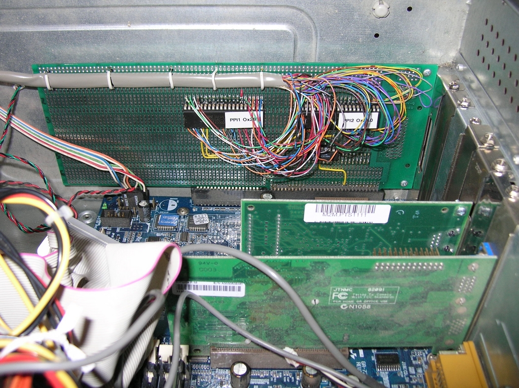
Figure 3. Homemade 48-Port ISA I/O Board
The AS2518 MPU is based on the Motorola 6800 microprocessor. It uses two 6820 Peripheral Interface Adapters (PIAs) to provide I/O to the rest of the system. The Intel 8255s are functionally similar. What must be duplicated on the interface board are the circuit elements between the PIA I/O lines and the header pins. These are determined through direct inspection and study of the electrical schematics accompanying the patents and the operator manuals, and consist mainly of resistors and capacitors. A picture of the board I created is shown in Figure 4. A label maker works great for marking wires and connectors.
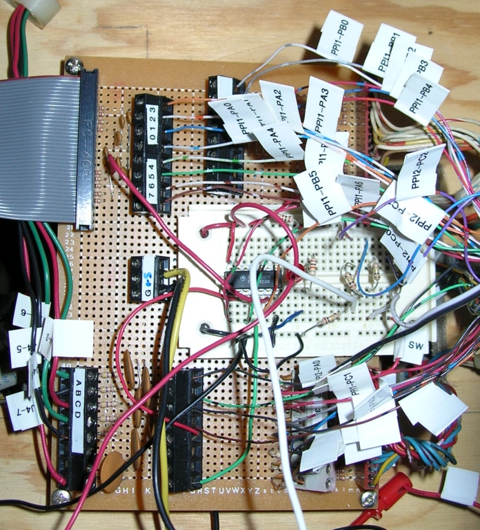
Figure 4. Interface Board
First, I tried to make the control system work as an ordinary user-space program. Using the method of divide and conquer, the simplest subsystem of the pinball machine to hack is the continuous solenoids. They are either on or off for long periods of time. On my game, I implemented only the flipper relay, which is turned on during normal game play and off when the game is over or tilted so that the flipper buttons don't do anything. This operation was easily accomplished by a variation of a C program I wrote to test the I/O board. According to the schematic, the flipper relay is enabled by making its output low rather than high. This is known as negative logic. I quickly learned something about the PC architecture: even with a pull-up resistor, the port is in a low state from the moment the computer is powered up. This had the unintended result of turning on the flippers before the control program was even started. To work around it, I added a 7404 inverter to the interface board. Now the flippers are enabled when the output is set high.
Next, in order of complexity, comes control of the momentary solenoids. These are things like the pop bumpers, chimes, slingshots, saucers and the outhole kicker that are fired for brief bursts throughout the game. The Bally documentation states most are energized for a period of 26 milliseconds; some, like the drop target reset, for twice as long. To fire one of 16 possible solenoids, five output lines are used to drive a 74LS154 decoder on the solenoid driver board. Four lines provide the binary representation of the desired solenoid, and one line enables or disables the decoder outputs. Each output in turn drives one of the 16 momentary solenoids.
Like the continuous solenoids, the 74LS154 enable uses negative logic. Programming this action seems simple. Start with the enable high. Output the four-bit solenoid number, set the enable low for the desired duration, then set it high again. Actually, this creates a problem that challenges the ability of an ordinary Linux user process to behave in real time. You cannot depend on usleep(26000) to produce a 26-millisecond delay precisely; it may and often does yield a longer delay, as the man page warns. Leaving a solenoid enabled for much longer than 100 milliseconds can damage it and blow the fuse. One option discussed in the Port Programming HOWTO is using multiple outb() calls, because each one takes approximately a microsecond to execute. However, this amounts to a colossal waste of CPU time spent in a busy loop.
The prospects for a user-space control process diminished even more as I began to implement the switch matrix. The Bally documentation explains that once every 8.3 milliseconds a snapshot of the switch matrix is created and then analyzed for changes, such as when the pinball strikes one of the many switches on the play field. It is a matrix because 40 separate switches are wired into five rows of eight columns apiece. The rows are outputs and the columns are inputs. A logical high is output to the first row, also referred to as strobing the row. After a brief delay to allow the voltage to be detected at the other end of the circuit, an input operation reads the eight, single-bit columns as one byte of data. Then the process repeats for the next row, and so on.
Here is where the real-time requirements become critical for correct game operation. If an adequate delay is not created between the row strobe and the column input, you get garbage; the game's closed-loop feedback system fails. If too much time elapses between each sample, such as while the process is swapped out by the scheduler, a switch closure might be missed. The challenge of ensuring that the control process executes at a high frequency (120 Hertz) led me away from user space to the kernel.
The module I wrote is based on the examples given in the excellent tutorial The Linux Kernel Module Programming Guide. Every kernel module requires an initialization function that is called when the module is installed via insmod. This is where I write out the control words to the two 8255 PPIs defining which ports are for input and which are for output. Here is also a good place to register a character device file, which is a simple means to communicate between kernel space and user space. I created one called /dev/pmrek.
To turn this module into a periodic process, I declared a workqueue for it. Workqueues are a new feature of the 2.6 kernel. The function in my device driver I want to call with the workqueue is pmrek_process_io(). The workqueue is defined at the global level of the module code with the statements:
static struct workqueue_struct * pmrek_workqueue;
static struct work_struct pmrek_task;
static
DECLARE_WORK(pmrek_task, pmrek_process_io, NULL);
Then, in the module initialization function pmrek_init(), create the workqueue with:
pmrek_workqueue = create_workqueue(pmrek_WORKQUEUE);
This does not actually schedule the workqueue yet. That happens when the supervisory program activates it. Figure 5 is a flowchart of the low-level hardware I/O operations performed by pmrek_process_io().
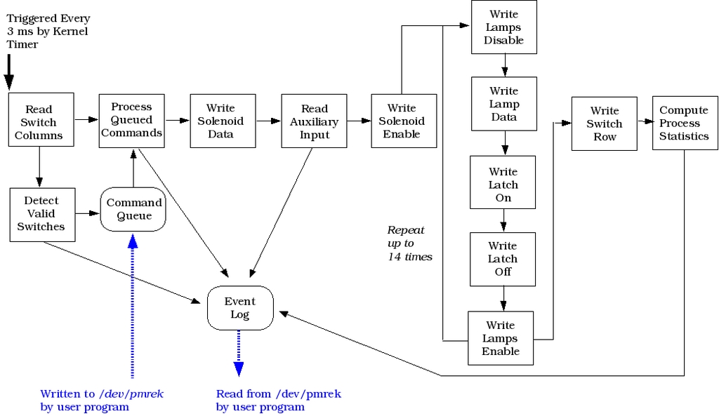
Figure 5. Kernel Workqueue Process Flowchart
The first thing it does is read in the switch columns using inb(). If there are any valid switch detections, they are written to a log buffer. This log buffer is consumed by the supervisory process, and game play advances depending on the switches detected. Switch detections are stamped with the exact time they occurred by getting the CPU Real Time Stamp Counter (RTSC) via the inline assembly command:
__asm__ volatile (".byte 0x0f, 0x31" : "=A" (cpu_time));
This sets cpu_time to the number of CPU machine cycles that have occurred since booting. It is handy for precise timing measurements. Some switches, such as the pop bumpers and slingshots, require an immediate solenoid response.
Next, any enqueued commands are executed in order by calling the function pmrek_process_commands(). Commands can be sent from the supervisory program by writing to /dev/pmrek, or they can originate in the module itself. If a momentary solenoid is to be fired, the four-bit solenoid number is output using outb(). Then the enable output is set high to turn on the 74LS154 decoder output. The enable duration is kept by a counter that is decremented by the workqueue process delay, which is three milliseconds. Thus, a 26-millisecond solenoid pulse will take eight workqueue cycles before the enable bit is set low again to turn it off.
Next, the control process services the feature lamps. The AS2518 architecture includes a lamp driver board populated with 60 silicon controlled rectifiers (SCRs) to turn on or off individual light bulbs selectively on the play field and back box. Like the momentary solenoids, these SCRs are driven by decoders that take a four-bit input and turn on one of 16 outputs. To handle all 60 feature lamps, there are four decoders. The control program steps through the 16 positions and selectively turns on any of the four lamps associated with it. All of this must be done at the beginning of every cycle of the 120-Hertz, rectified DC power supply waveform. On the AS2518, this is accomplished using an interrupt triggered by a power supply zero-crossing detector. I decided not to use an interrupt. Instead, I employed a “shotgun” method by executing the control process at double this rate or faster, ensuring that the SCRs are triggered every cycle.
The last I/O operation performed by the workqueue process is to output the next row strobe for the next reading of the switch matrix. Then the process reschedules itself by issuing the command:
queue_delayed_work(pmrek_workqueue,
                   &pmrek_task,
                   pmrek_i.workqueue_delay);
The data structure pmrek_i contains all sorts of information about the pinball control system, including its workqueue delay, which has a value of 3. The kernel timer runs at 1,000Hz and is the heartbeat of the kernel. The workqueue delay is the number of beats before the delayed work is executed. Using this mechanism, frequencies much higher than what can be scheduled for ordinary user processes outside the kernel can be achieved, and they are more efficient in terms of the resources they use each time they execute.
Not everything in the pinball machine control system has to execute as frequently as the low-level hardware I/O operations. Game play itself—how the machine responds to switch detections, lighting different lamps and incrementing the player scores—operates just fine as an ordinary user process. In a sense, it is really a supervisory controller of the low-level I/O processing.
The kernel module should work for every game based on the AS2518 MPU. You can download the source code from the Pinball Machine Reverse-Engineering Kit Project on SourceForge.net and compile it for your kernel. It will then be up to you to write the supervisory control software to play the particular game you are hacking. Table 1 lists other source code files in this package.
Table 1. Source Code for the Pinball Machine Reverse-Engineering Kit
| Source Code File | Purpose |
|---|---|
| analyze_testbed_output.php | Analyzes a game using the parsed text file output of user_pmrek.exe and the saved system activity records. |
| common_functions.php | Functions shared by PHP programs. |
| Makefile_pmrek | GNU Make command file to compile kernel module and executables. |
| pmrek_bash_profile | Appended to auto-login user's bash profile; calls start_testbed. |
| pmrek.c | Linux 2.6 kernel module for hardware control process. |
| pmrek.h | Header file containing definitions and data structures. |
| pmrek.sql | MySQL script to create database, tables and access permissions. |
| start_testbed | Shell script for running standalone testbed system; runs testbed.exe and restarts if terminated for upgrade. |
| testbed.c | Supervisory process for controlling kernel module, playing Evel Knievel, logging and analyzing process data; compiles into the executable testbed.exe. |
| testbed_performance.php | Creates summary statistics of all games analyzed. |
| user_pmrek.c | Utility program for parsing output of testbed.exe, displaying data structure sizes and simulating operation of the kernel module; compiles into the executable user_pmrek.exe. |
You are free to modify the C program testbed.c I wrote for Evel Knievel. It uses the ncurses screen handling package to provide a console color display and user input. A diagnostic display shows the disposition of the switch matrix, the lamps and the most recently fired solenoid. It also shows the player scores, as well as run-time statistics such as the average cycle frequency and execution time of the kernel workqueue process. Keyboard commands can be entered to turn the continuous solenoid on or off, fire momentary solenoids, turn feature lamps on or off and adjust the workqueue delay. Figure 6 shows a game in progress. Note the closed switches; these are drop targets that have been struck.
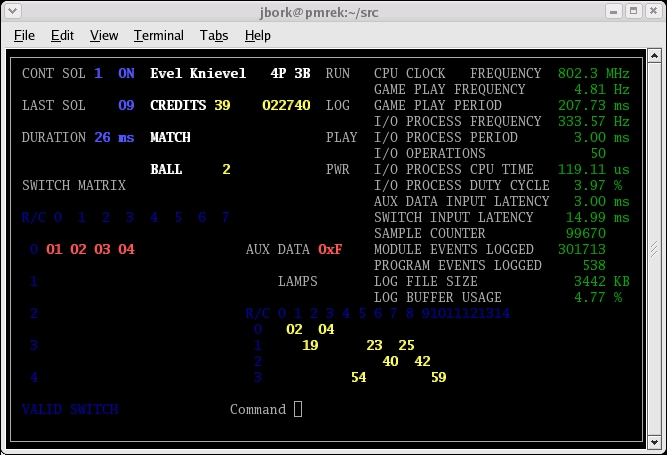
Figure 6. Supervisory Program Diagnostic Display
The supervisory program receives events passed from the kernel module by reading /dev/pmrek, which it has opened using the system call open(), just like any other file. Commands are then sent back to the module by writing to it. I tried to make the main functions correspond to my impression of the key events in a game of pinball. They are listed in Table 2.
Table 2. Supervisory Control Program Functions
| Function Name | Purpose |
|---|---|
| game_add_player() | Called when the credit button is pressed (and there are credits) to start a new game or add more players. |
| game_ball_end() | Called when the outhole switch is detected while a ball is in play to initiate the bonus countdown, advance to the next ball, the next player or end the game. |
| game_collect_bonus() | Called after a ball ends to count down the current player's bonus. |
| game_segment_display() | Emulation of a seven-segment digital display on the computer screen for player scores, match count, credits and ball in play. |
| game_lamp_update() | Called after processing switch detections to update the disposition of all the feature lamps at once. |
| game_play_tune() | Plays various tunes by firing the chime momentary solenoids in predefined sequences. |
| game_switch_response() | Called for each valid switch detection retrieved from the kernel module; initiates all other events related to normal game operation. |
| game_watchdog() | Called every second to detect game faults, including missed switch detections, and either reprocesses the switch response or terminates the program. |
| process_output_file() | Called by the forked child process after a game is completed to analyze the log file recorded during the game play. |
| termination_handler() | Signal handler for cleanly ending the program; closes data log file and puts the kernel module into an idle state. |
| main() | Main program initializes kernel module data structures, computer screen and loops until a termination signal is caught; main loop processes user keyboard input, reads events from kernel module, calls game process functions, writes log file to disk and updates computer screen display. |
You should be able to adapt this code to your particular game by tweaking the functions game_switch_response() and game_lamp_update(). How do you write the program without peeking at the original manufacturer's source code? There are plenty of clues painted on the play field itself, telling you what each switch scores and so on. Of course, you also can create your own rules, perhaps improving on weaknesses in the original design.
The diagnostic display is great for testing, but the player scores are too small. By default, the console simulates the large digital displays on the original back box, as shown in Figure 7. You can get to the diagnostic display by pressing the Self Test switch inside the pinball machine coin door.
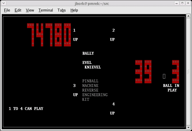
Figure 7. Back Board Score Display
We took the game to Pinball at the Zoo in Kalamazoo, Michigan in April 2005. Hundreds of people played the game, which collected statistical data that I used in my Master's thesis. After each game completes, a PHP program reads through the log file created by the game program. It generates an HTML document summarizing the event history of the game and statistics about its real-time performance. These results are then stored in a MySQL database to facilitate analysis of overall performance. Figure 8 is a block diagram of the setup. Figure 9 shows the game in action.
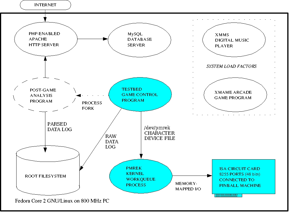
Figure 8. Computer System Block Diagram
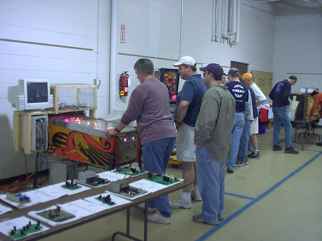
Figure 9. Game in Action at Pinball at the Zoo
This project is a success story for the Linux 2.6 kernel. It demonstrates that a complex, real-time process control application can be created using a kernel workqueue instead of a complicated hardware interrupt or an additional, real-time package like RTLinux. Furthermore, through the choice of a pinball machine, a jack-of-all-trades hacker can produce something truly useful and fun to play.
Resources for this article: /article/8529.
John R. Bork is an IT System Integrator at Marathon Petroleum Company in Findlay, Ohio. He has been hacking Linux and pinball machines since 1999.