
MyHDL: a Python-Based Hardware Description Language
Digital hardware design typically is done using a specialized language, called a hardware description language (HDL). This approach is based on the idea that hardware design has unique requirements. The mainstream HDLs are Verilog and VHDL.
The MyHDL Project challenges conventional wisdom by making it possible to use Python, a high-level, general-purpose language, for hardware design. This approach lets hardware designers benefit from a well-designed, widely used language and the open-source model behind it.
An HDL contains certain concepts that reflect the nature of hardware. The most characteristic concept is a model for massive concurrency. An HDL description consists of a large amount of tiny threads that communicate closely with one another. This design calls for an approach to threading that is as lightweight as possible. HDL descriptions are executed on a dedicated runtime environment called a simulator.
When designing MyHDL, I took a minimalistic approach, which is in line with the Python spirit and a good idea in general. Therefore, an important part of MyHDL is a usage model for Python. The other part consists of a Python package, called myhdl, that contains objects that implement HDL concepts. The following Python code imports some MyHDL objects that we are going to use shortly:
from myhdl import Signal, Simulation, delay, now
MyHDL models concurrency with generator functions, recently introduced in Python (see the on-line Resources). They are similar to classic functions, except they have a nonfatal return capability. When a generator function is called, it returns a generator, which is the object of interest. Generators are resumable and keep state between invocations, making them usable as ultra-lightweight threads.
The following example is a generator function that models a clock generator:
    def clkgen(clk):
        """ Clock generator.
        clk -- clock signal
        """
        while 1:
            yield delay(10)
            clk.next = not clk
This function looks similar to a classic function in Python. Notice that the functional code starts with a while 1 loop; this is the idiomatic way to keep a generator alive forever. The essential difference between a classic and a generator function is the yield statement. It behaves similarly to a return statement, except the generator remains alive after yielding and can be resumed from that point. Moreover, the yield statement returns a delay object. In MyHDL, this mechanism is used to pass control information to the simulator. In this case, the simulator is informed that it should resume the generator after a delay of ten time units.
The parameter clk represents a clock signal. In MyHDL, signals are used for communication among generators. The concept of a signal is inherited from VHDL. A signal is an object with two values: a read-only current value and a next value that can be modified by assigning it to the .next attribute. In the example, the clock signal is toggled by setting its next value to the inverse of its current value.
To simulate the clock generator, we first create a clock signal:
clk = Signal(bool(0))
The signal clk has a Boolean zero as its initial value. Now, we can create a clock generator by calling the generator function:
clkgen_inst = clkgen(clk)
To have a minimally useful simulation, let's create another generator that monitors and prints the changes of the clock signal over time:
def monitor():
    print "time: clk"
    while 1:
        print "%4d: %s" % (now(), int(clk))
        yield clk
The yield clk statement shows how a generator can wait on a change of the signal value.
In MyHDL, a simulator is created with the Simulation object constructor, which takes an arbitrary number of generators as parameters:
sim = Simulation(clkGen_inst, monitor())
To run the simulator, we call its run method:
sim.run(50)
This runs the simulation for 50 time units. The output is as follows:
$ python clkgen.py
time: clk
   0: 0
  10: 1
  20: 0
  30: 1
  40: 0
  50: 1
At this point, we can describe how the simulator works. The simulation algorithm is inspired by VHDL, an HDL slightly less popular than Verilog but a better example to follow. The simulator coordinates the parallel execution of all generators using an event-driven algorithm. The object that a generator yields specifies the event for which it wants to wait before its next invocation.
Suppose that at a given simulation step, some generators become active because the event they were waiting on has occurred. In a first simulation phase, all active generators are run, using current signal values and assigning to next values. In a second phase, the current signal values are updated with the next values. As a result of signal value changes, some generators become active again, and the simulation cycle repeats. This mechanism guarantees determinism, because the order in which the active generators are run is irrelevant for the behavior of the model.
Having introduced the concepts, we now are ready to tackle a real design example with MyHDL. I have chosen a serial peripheral interface (SPI) slave hardware module. SPI is a popular synchronous serial control interface originally designed by Motorola.
A single SPI master can control multiple slaves. There are three common I/O ports: mosi, the master-out, slave-in serial line; miso, the master-in, slave-out serial line; and sclk, the serial clock driven by the master. In addition, a slave select line, ss_n, exists for each slave. SPI communication always occurs in the two directions simultaneously. In general, the active clock edge that triggers data changes is configurable. In this example, we use the rising edge.
The MyHDL code of the SPI slave is shown in Listing 1. A classic Python function called SPISlave is used to model a hardware module. The function has all interface signals as its parameters, and it returns two generators. This code illustrates how hierarchy is modeled in MyHDL: a higher-level function calls lower-level functions and includes the returned generators in its own return value.
Listing 1. MyHDL Model of an SPI Slave
from myhdl import Signal, posedge, negedge, intbv

ACTIVE_n, INACTIVE_n = bool(0), bool(1)
IDLE, TRANSFER = bool(0), bool(1)

def toggle(sig):
    sig.next = not sig

def SPISlave(miso, mosi, sclk, ss_n,
             txdata, txrdy, rxdata, rxrdy,
             rst_n, n=8):
    """ SPI Slave model.

    miso -- master in, slave out serial output
    mosi -- master out, slave in serial input
    sclk -- shift clock input
    ss_n -- active low slave select input
    txdata -- n-bit input with data to be transmitted
    txrdy -- toggles when new txdata can be accepted
    rxdata -- n-bit output with data received
    rxrdy -- toggles when new rxdata is available
    rst_n -- active low reset input
    n -- data width parameter

    """

    cnt = Signal(intbv(0, min=0, max=n))

    def RX():
        sreg = intbv(0)[n:]
        while 1:
            yield negedge(sclk)
            if ss_n == ACTIVE_n:
                sreg[n:1] = sreg[n-1:]
                sreg[0] = mosi
                if cnt == n-1:
                    rxdata.next = sreg
                    toggle(rxrdy)

    def TX():
        sreg = intbv(0)[n:]
        state = IDLE
        while 1:
           yield posedge(sclk), negedge(rst_n)
            if rst_n == ACTIVE_n:
                state = IDLE
                cnt.next = 0
            else:
                if state == IDLE:
                    if ss_n == ACTIVE_n:
                        sreg[:] = txdata
                        toggle(txrdy)
                        state = TRANSFER
                        cnt.next = 0
                else: # TRANSFER
                    sreg[n:1] = sreg[n-1:]
                    if cnt == n-2:
                        state = IDLE
                    cnt.next = (cnt + 1) % n
                miso.next = sreg[n-1]

    return RX(), TX()
The module interface contains some additional signals and parameters. txdata is the input data word to be transmitted, and txrdy toggles when a new word can be accepted. Similarly, rxdata contains the received data word, and rxrdy toggles when a new word has been received. Finally, there is a reset input, rst_n, and a parameter n that defines the data word width.
Inside the SPI slave module, we create a signal, cnt, to keep track of the serial cycle number. It uses an intbv object as its initial value. intbv is a hardware-oriented class that works like an integer with bit-level facilities. Python's indexing and slicing interface can be used to access individual bits and slices. Also, an intbv object can have a minimum and a maximum value.
The RX generator function describes the receive behavior. Whenever the slave select line ss_n is active low, the mosi input is shifted to the shift register sreg. The yield negedge(sclk) statement indicates that the action occurs on the falling clock edge. In the last serial cycle, the shift register is transferred to the rxdata output and rxrdy toggles.
The TX generator function is slightly more complicated, because it requires a small state machine to control the protocol. The yield statement specifies two events in this case, meaning that the generator is resumed on the event that occurs first. When the reset input is active low, cnt and state are reset. In the other case, the action depends on the state. In the IDLE state, we wait until the select line goes active low before accepting the data word for transmission and going to the TRANSFER state. In the TRANSFER state, the shift register is shifted out serially. The state machine maintains the proper serial cycle count and returns to the IDLE state on the last shift.
The SPI slave module was modeled at a level that stays close to an actual implementation. This is a good way to introduce MyHDL's concepts. However, using MyHDL for this purpose doesn't provide a lot of advantages over traditional HDLs. Instead, MyHDL's real value is it makes the whole of Python available to hardware designers. Python's expressive power, flexibility and extensive library offer possibilities beyond the scope of traditional HDLs.
One area in which Python-like features are desirable is verification. As with software, in hardware design, verification is the hard part. It generally is acknowledged that traditional HDLs are not up to the task. Consequently, yet another language type has emerged, the hardware verification language (HVL). Once again, MyHDL relies on Python to challenge this trend.
To set up a hardware verification environment, we first create a test bench. This is a hardware module that instantiates the design under test (DUT), together with data generators and checkers. Listing 2 shows a test bench for the SPI slave module. It instantiates the SPI slave module together with an SPI tester module that controls all interface pins. To be able to use multiple SPI tester modules that verify various aspects of the design, the SPI tester module is a parameter of the test bench.
Listing 2. A Test Bench for the SPI Slave Module
import unittest
from random import randrange

from myhdl import Signal, intbv, traceSignals

from SPISlave import SPISlave, ACTIVE_n, INACTIVE_n

def TestBench(SPITester, n):

    miso = Signal(bool(0))
    mosi = Signal(bool(0))
    sclk = Signal(bool(0))
    ss_n = Signal(INACTIVE_n)
    txrdy = Signal(bool(0))
    rxrdy = Signal(bool(0))
    rst_n = Signal(INACTIVE_n)
    txdata = Signal(intbv(0)[n:])
    rxdata = Signal(intbv(0)[n:])

    SPISlave_inst = traceSignals(SPISlave,
        miso, mosi, sclk, ss_n,
        txdata, txrdy, rxdata, rxrdy, rst_n, n=n)

    SPITester_inst = SPITester(
        miso, mosi, sclk, ss_n,
        txdata, txrdy, rxdata, rxrdy, rst_n, n=n)

    return SPISlave_inst, SPITester_inst
For the tests themselves, we use a unit testing framework. Unit testing is a cornerstone of extreme programming (XP), a modern software development methodology that is an intriguing mixture of common sense and radically new ideas. The genuine XP approach is to develop the test first, before the implementation. XP is a useful methodology, but its lessons virtually are ignored by the hardware design community. With MyHDL, Python's unit testing framework, unittest, can be used for test-driven hardware development.
Listing 3 shows test code for the SPI slave module. Tests are defined in a subclass of the unittest.TestCase class. Each method name with the prefix test corresponds to an actual test, but other methods can be written to support the tests. A typical test suite consists of multiple tests and test cases, but we describe a single test to demonstrate the idea.
Listing 3. A Test Case for Receiving Data via SPI
import unittest
from random import randrange

from myhdl import Simulation, join, delay, \
                  intbv, downrange

from SPISlave import SPISlave, ACTIVE_n, INACTIVE_n
from SPISlaveTestBench import TestBench

n = 8
NR_TESTS = 100

class TestSPISlave(unittest.TestCase):

    def RXTester(self, miso, mosi, sclk, ss_n,
                 txdata, txrdy, rxdata, rxrdy,
                 rst_n, n):

        def stimulus(data):
            yield delay(50)
            ss_n.next = ACTIVE_n
            yield delay(10)
            for i in downrange(n):
                sclk.next = 1
                mosi.next = data[i]
                yield delay(10)
                sclk.next = 0
                yield delay(10)
            ss_n.next = INACTIVE_n

        def check(data):
            yield rxrdy
            self.assertEqual(rxdata, data)

        for i in range(NR_TESTS):
            data = intbv(randrange(2**n))
            yield join(stimulus(data), check(data))

    def testRX(self):
        """ Test RX path of SPI Slave """
        sim = Simulation(TestBench(self.RXTester, n))
        sim.run(quiet=1)

if __name__ == '__main__':
    unittest.main()
The RXTester method is a generator function designed for a basic test of the SPI slave receive path. It contains a local generator function, stimulus, that transmits a data word on the SPI bus as a master. Another local generator function, check, checks whether the data word is received correctly by the slave. The complete test consists of a number of random data word transfers. For each data word, we create a stimulus and a check generator. To wait for their completion, MyHDL allows us to put them in a yield statement. For proper synchronization, we want to continue only when both generators have completed. This functionality is accomplished by the join function.
When we run the test program, the output indicates which tests fail at what point. When everything works, the output from our small example is as follows:
$ python test_SPISlave.py -v
Test RX path of SPI Slave ... ok
------------------------------------------------
Ran 1 test in 0.559s
MyHDL supports waveform viewing, a popular way to visualize hardware behavior. In Listing 2, the instantiation of the SPI slave module is wrapped in a call to the function traceSignals. As a side effect, signal changes are dumped to a file during simulation, in a standard format. Figure 1 shows a sample of the waveforms rendered by gtkwave, an open-source waveform viewer.
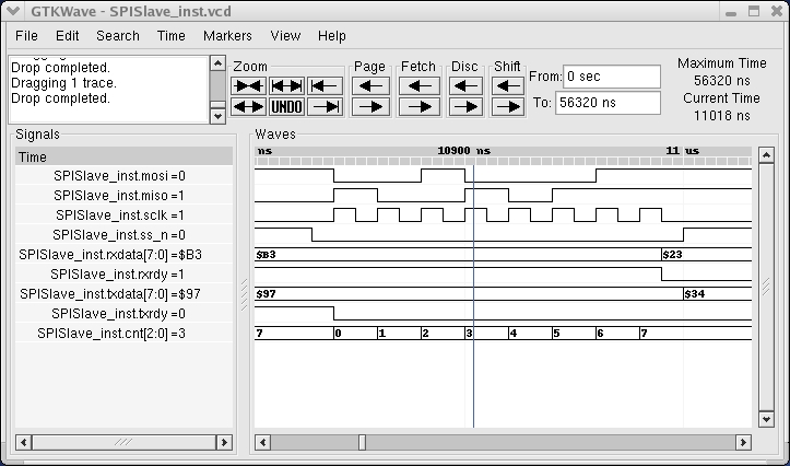
Figure 1. Using gtkwave, you can visualize all the signals as the test suite runs.
MyHDL is a practical solution with links to other HDLs. MyHDL supports co-simulation with other HDL simulators that have an interface to the operating system. A bridge must be implemented for each simulator. This has been done for the open-source Verilog simulators Icarus and cver.
In addition, an implementation-oriented subset of MyHDL code can be converted automatically into Verilog. This is done with a function called toVerilog, which is used in the same way as the traceSignals function described earlier. The resulting code can be used in a standard design flow, for example, to synthesize it automatically into an implementation.
Tim Peters, a famous Python guru, explains his love for Python with the paradoxical statement, “Python code is easy to throw away.” In the same spirit, MyHDL aims to be the hardware design tool of choice to experiment with new ideas.
Resources for this article: /article/7749.
Jan Decaluwe has been an ASIC design engineer and entrepreneur for 18 years. Currently, he is an electronic design and automation consultant. He can be reached at jan@jandecaluwe.com.
