
Analyzing Circuits with SPICE on Linux
SPICE is the Simulation Program with Integrated Circuit Emphasis, first released from the University of California at Berkeley in the early 1970s. Before the existence of SPICE engineers designed circuits by hand, possibly with the aid of a slide-rule or calculator. A prototype was constructed from the original design, and its performance evaluated against the designer's goals.
Designing many of today's circuits would be impossible without the aid of SPICE. Frequently analog circuits contain hundreds or thousands of devices. Design and analysis involve finding solutions to simultaneous equations. These equations can be of simple algebraic form or involve nonlinear differential equations. Prototypes are still constructed to gauge performance, but given costs running in the hundreds of thousands of dollars, performance must be largely anticipated through computer simulation before prototype fabrication begins.
SPICE is not limited to integrated circuit design. Rather, SPICE is useful for analyzing any circuit which can be described in terms of voltage sources, current sources, resistors, capacitors, inductors, transistors and a few other components.
SPICE version 3f4 was released in 1993, and the source code is freely available to those friendly to the U.S.A. You can get a copy of the source code from ftp://sunsite.unc.edu/pub/Linux/apps/circuits/spice3f4.tar.gz.
I run Red Hat Linux and use the Red Hat Package Manager (rpm). If you're running rpm, you can take advantage of Andrew Veliath's spice-3f4-2.src.rpm package. You can find a copy on ftp.redhat.com and mirrors. If you don't use rpm, you might want to consider building it and using rpm2cpio to unpack the spice-3f4-2.src.rpm package, since it contains two very useful patches to the pristine source for building on Linux systems.
If you're using rpm, building SPICE is as easy as:
rpm -ba -vv SRPMS/spice-3f4-2.src.rpm
rpm -i -U -vv RPMS/i386/spice-3f4-2.i386.rpm
The first line builds the installable package from the source package. The second line installs the package and updates the rpm database.
If you're not using rpm, building and installing SPICE is a little more involved but not too bad. The basic process is as follows:
rpm2cpio SRPMS/spice-3f4-2.src.rpm | cpio -i
tar xzpf spice3f4.tar.gz
patch < spice3f4.newlnx.patch
patch < spice3f4.dirs.patch
cd spice3f4
util/build linux
Compiling took 12 minutes on my 200MHz Pentium system.
util/build linux install
strip /usr/bin/{spice3,help,nutmeg,sconvert,multidec,\
        proc2mod}
install -m 644 man/man1/spice.1 /usr/man/man1
install -m 644 man/man1/nutmeg.1 /usr/man/man1
install -m 644 man/man1/sconvert.1 /usr/man/man1
install -m 644 man/man3/mfb.3 /usr/man/man3
install -m 644 man/man5/mfbcap.5 /usr/man/man5
After installation comes the real fun—creating and simulating
circuits. While a minimal Linux system can run SPICE adequately,
analysis time can be significantly improved when it is run on a
system with a fast processor(s), 133MHz or above. Additional RAM is
equally important, especially for larger circuits. I have 32MB in
my home Linux/Pentium system and 128MB in my SunOS/Sparc20 at work.
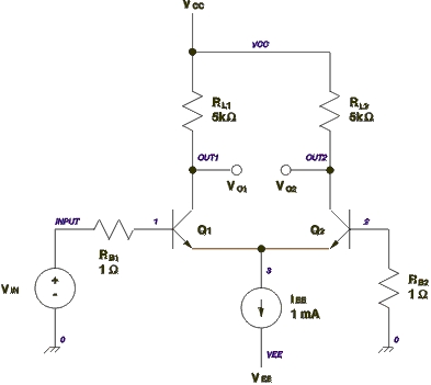
Figure 1. Differential Pair Circuit Schematic
Figure 1 shows a the schematic of a differential pair circuit constructed from bipolar junction transistors and resistors. This circuit can be used for either digital or analog purposes and, in either case, can be simulated using SPICE. The circuit operates in the following manner. Very little current flows through the base of transistor Q2, so the base can be considered to be held near ground potential, zero volts. When the input voltage, VIN, is low, near ground, Q1 will be off and Q2 will be on. No current will flow through Q1, so VO1 will be high, equal to VCC. All of the current in IEE will flow through Q2. The voltage drop across RL2 will be:

So the voltage VO2 will be 5V below VCC. So, VO2 will be 0V.
In linear analog operation VIN will be held near ground except for small signal excursions away from ground. Under this condition the differential pair will serve as an amplifier where the voltage gains are:
AV1 = VO1 / VIN = -(gm1/2) * RL1
AV2 = VO2 / VIN = (gm2/2) * RL2
where gm1 and gm2 are the transconductances of the two transistors. These values can easily be calculated by hand, but since the point of this story is to show SPICE at work, we'll let SPICE tell us the transconductance values.
Listing 1 shows the SPICE input file corresponding to the circuit in Figure 1. The SPICE input file contains a description of the circuit and its connections, input stimuli, statements to control what kind of analysis SPICE will perform, statements to control output, comments and a title. The first line is always the title and the last non-blank line is always .end. Comment lines begin with an asterisk (*). Control lines of any kind begin with a period (.). The line continuation character is a plus sign (+) which goes at the beginning of a line being continued from the previous line. This is a little different from the common backslash (\) line continuation, used elsewhere in Linux, where that continuation character goes at the end of the line being continued on the next line.
The options lines shown here:
 .opt nopage
 .width in=72
 .width out=80
specify that no page breaks will be in the generated output text and the line length of the input and output text. The first line below instructs SPICE to perform a DC analysis of the circuit where VIN is run from -0.15V to 0.15V in 0.010V increments. The next line tells SPICE to generate operating point information for the circuit. It is this line that reports the transconductances of each transistor.
.dc vin -0.15 0.15 0.010
.op
The middle half of the input file describes the connection of circuit elements and sources. In SPICE connection points are termed nodes. Every SPICE circuit must contain a ground node numbered zero.
iee 3 vee 1m
iee is a current source, known to SPICE by the leading i, where 1mA of current flows from node 3 toward the vee node.
vin input 0 0 sin(0 0.3 5meg) ac 1
vin is the input voltage source connected at the positive end to the input with the negative end connected to ground. The DC value of the input voltage is 0V. The time varying—“transient” in SPICE jargon—portion of the input voltage is a sine wave centered at 0V with an amplitude of 0.3V oscillating at a frequency of 5MHz. The AC portion of the input will be normalized to 1V. That is, the AC analysis in SPICE doesn't exercise large signal behavior of the circuit. Digital behavior is the extreme of large signal behavior. Large signal performance of a circuit can be simulated using transient analysis in SPICE.
rl1 out1 vcc 5k
rl1 is a resistor connected between the out1 and vcc nodes with a value of 5k.
q1 out1 1 3 bjt
q1 is a bjt model instance with collector, base and emitter connections at nodes out1, 1 and 3 respectively. The model definition below names a model bjt of the type npn and with specific parameters. SPICE knows about npn transistors and a number of other types of circuit elements. This definition makes use of line continuation.
.model bjt npn(bf=80 rb=100 ccs=2pf
+   tf=0.3ns tr=6ns cje=3pf cjc=2pf
+   va=50)
The .plot line in Listing 1 tells SPICE to plot the voltage values at nodes out1 and out2 calculated during the DC analysis.
This command will run a SPICE analysis using the input file from Listing 1 named diffpair-1.cir:
spice3 -b diffpair-1.cir
The -b option causes SPICE to run in batch mode. Listing 2 shows the output of the SPICE analysis. The operating point information gives the DC bias voltages for all the nodes in the circuit and the current through every voltage source. A customary trick to measure current is to insert a voltage source whose voltage is zero. This does not hinder simulated performance, but the circuit will simulate slightly slower, since there's more in it. Model parameters are reported for each type of circuit model used in the simulation. Operating characteristics for the two bjt instances show the transconductance of each transistor to be 0.0191 A/V.
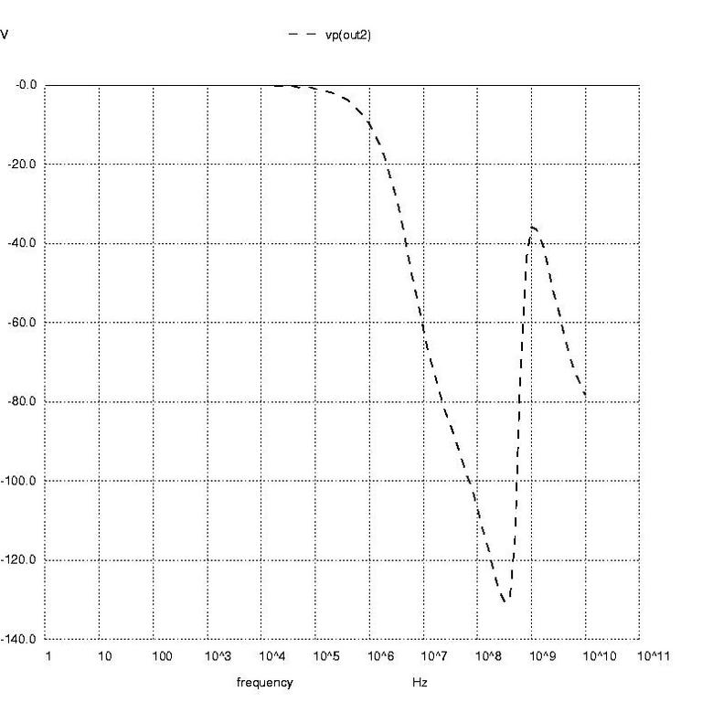
Figure 3: AC Analysis Plot in Degrees
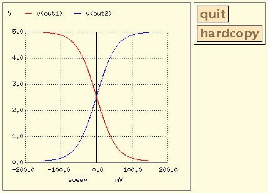
The DC transfer characteristic plot shows output voltage, from left to right, ranging over 0V to 5V and shows the input voltage, from top to bottom, ranging from -0.15V to +0.15V. Each time I view a plot like this I get nostalgic, recalling the days when I would flip switches on the front panel of a PDP-8 and load boot programs from paper tape. But that's another story. This plot certainly isn't fancy by today's standards, but it does convey the necessary information.
Finally, SPICE reports that the simulation took just under 1/10th of a second to run.
Listing 3 adds more analysis directives to the SPICE input file from Listing 1. The analyses to be performed are DC, transfer function, AC and transient. This time we'll start SPICE with an option to save the resulting data to a file, like so:
spice3 -b -r diffpair-2.raw diffpair-2.cir
After running SPICE the data file can be perused with nutmeg, which comes with the SPICE package. Start nutmeg simply by running
nutmeg diffpair-2.raw
Listing 4 captures an interactive session with nutmeg. At the first nutmeg prompt I entered setplot to give me the names of analysis data sets within the raw data file. I selected dc1 and then plotted the output voltages, shown in Figure 2. When plotted in this way, you can zoom in on sections of the plot using the right mouse button to define the zoomed plot's borders. You can also find the coordinates of any point on the plot or pair of points by either clicking or clicking and dragging the left mouse button. The coordinates display in the window where nutmeg runs. You can put labels on the plot by typing with the keyboard. By setting the type of hard copy device appropriately you can save the plot in a file for later printing, as shown in nutmeg commands 3 through 5.
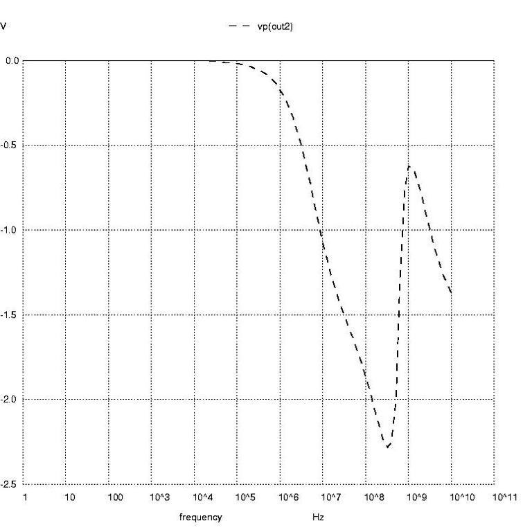
Figure 4: AC Analysis Plot in Radians
Next, in Listing 4, I selected the transfer function data. The display command shows me the variables I can query from the transfer function data. At prompt number 9 I asked to see the transfer function that SPICE reports to be 44.60971. This differs somewhat from the idealized gain equation, which neglects output resistance of the bjt.

Rather than just selecting one variable for display, at prompt number 10 I selected all variables for display. This shows the output impedance to be about.

, and the input impedance to be about

Nutmeg prompts 11 through 16 create the AC analysis plots of voltage phase at node out2 in degrees, voltage phase at node out2 in radians and magnitude of the voltage at node out2. These are shown in Figures 3 through 5, respectively.
Prompts 17 through 19 resulted in Figure 6, which shows the input voltage sine wave and the output voltage sine wave. Notice that the output voltage shows distortion of an over-driven amplifier.
At prompt 20 I ran a Fourier analysis on the time domain voltage to find the harmonic content of the distorted sine wave. I had to specify the fundamental frequency as 5MHz, the same as was given in the input file, and the node voltage the Fourier analysis should inspect. As expected from the compressed shape of the output sine wave, the total harmonic distortion (THD) is quite high.
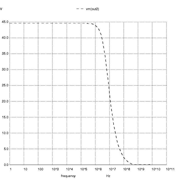
Figure 5: AC Analysis Plot as a Function of Magnitude
If you're going to have trouble with SPICE, most likely it will be with a circuit you can't analyze. The good news is that SPICE3 is improved in this respect, and you have some control over how numerical solutions are determined. When SPICE calculates node voltages and branch currents, it uses thresholds for tolerable errors to determine when a simulation reaches its answer—that is, when it reaches numerical convergence. The three parameters controlling the thresholds can be set on the .options statement and are named ABSTOL, VNTOL and RELTOL. ABSTOL is the smallest current you want SPICE to accept. Increasing ABSTOL from its default value of 12pA can help a simulation to converge. VNTOL is the smallest voltage that you want SPICE to accept. Increasing VNTOL from its default value of 10V can help a simulation to converge. RELTOL is the ratio of the numerical answer found during the present iteration to the numerical answer found during the last iteration. Increasing RELTOL can help a DC analysis to converge, but increasing RELTOL can also cause transient analysis problems. If you get a warning from SPICE saying “timestep too small”, RELTOL is probably set too large.
The parameters ITL1 through ITL6 control the number of iterations to perform before SPICE gives up, and control methods are used to attain convergence.
Obviously the accuracy of the simulation results can be no better than the convergence thresholds used during analysis. If you don't need to relax the thresholds, this won't present a problem since the tolerances on component values and variations in component performance stand to present much more discrepancy between nominal simulated performance and real-world measured performance.
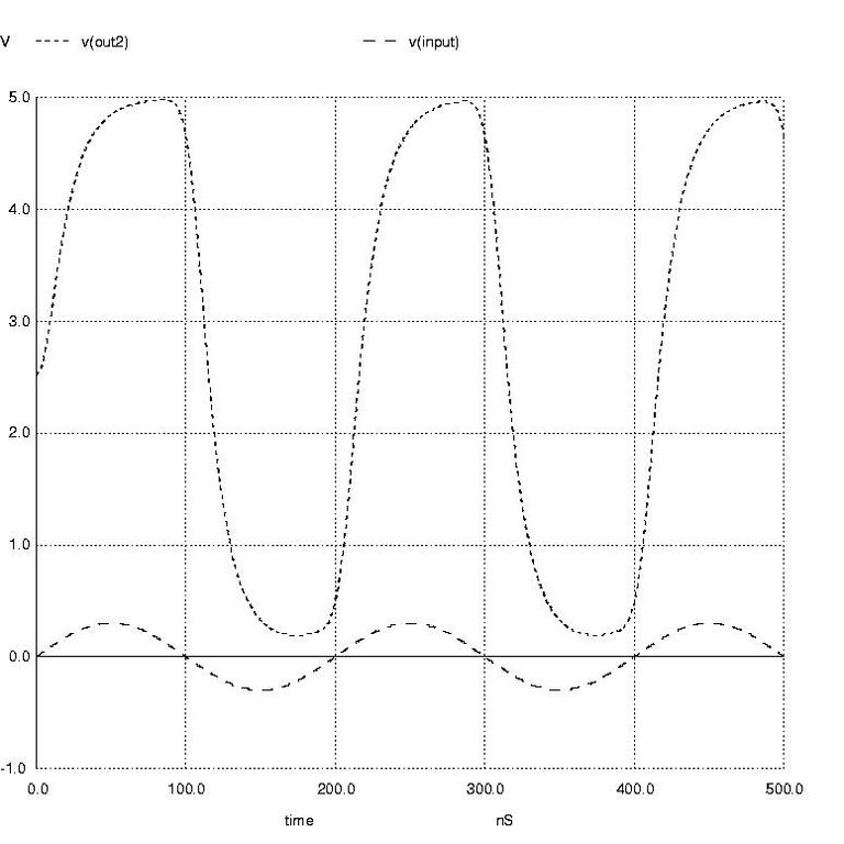
Figure 6: Input and Output Voltage Sine Wave
This article is far from an exhaustive treatment of what SPICE can do for you and how to use it to its fullest advantage. SPICE is both prevalent and useful to engineers, and has been so for nearly 30 years. If you never use SPICE, I hope you caught at least a glimpse of an engineer's bread and butter. If you use or will use SPICE, I hope this article gave you some insight into its use on Linux machines.


